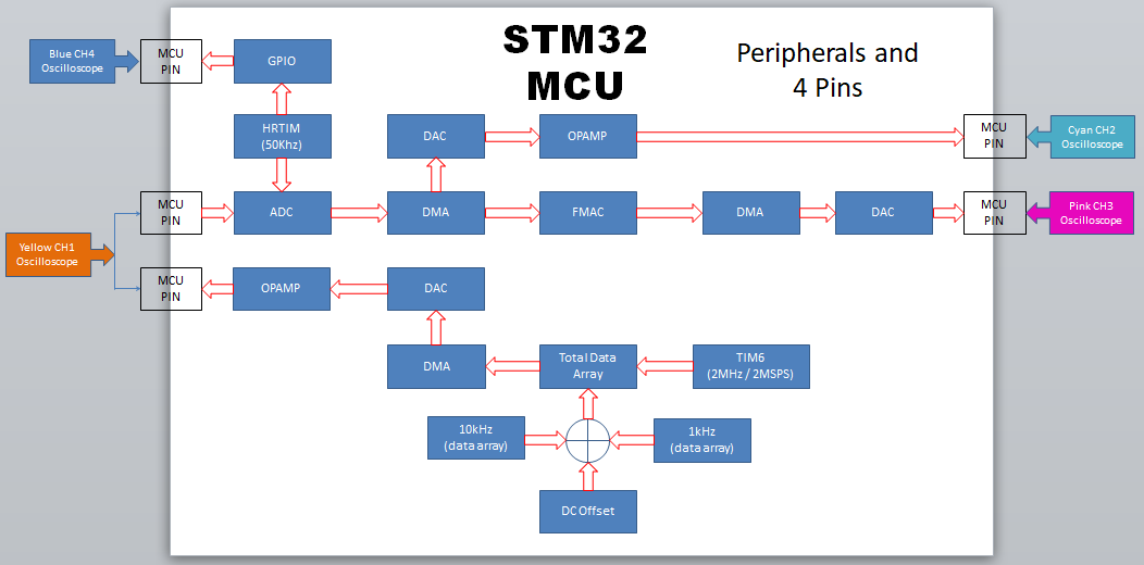
Test Realtime FIR/IIR (Low and High) Filter using FMAC (Filter Math ACCcelerator). The FMAC unit is built around a fixed point multiplier and accumulator (MAC).
IIR Filter is still a work in progress.
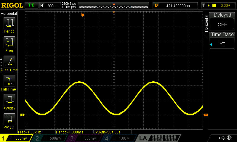
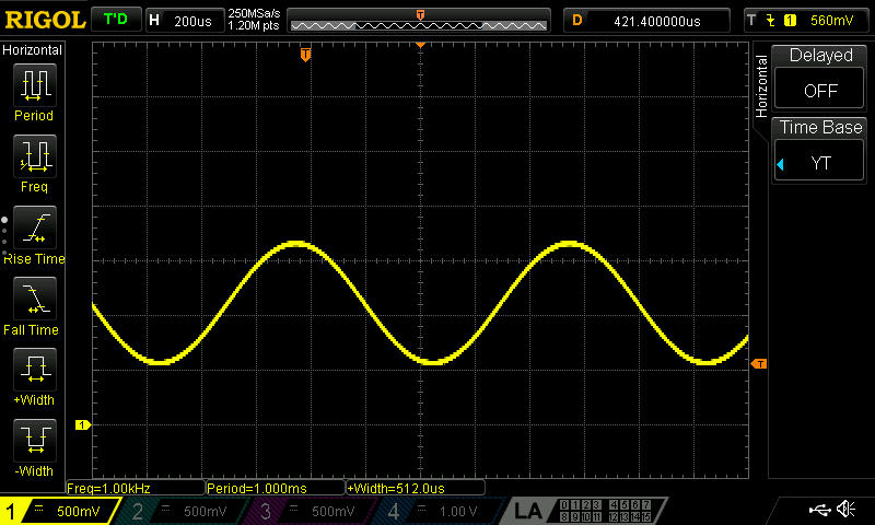
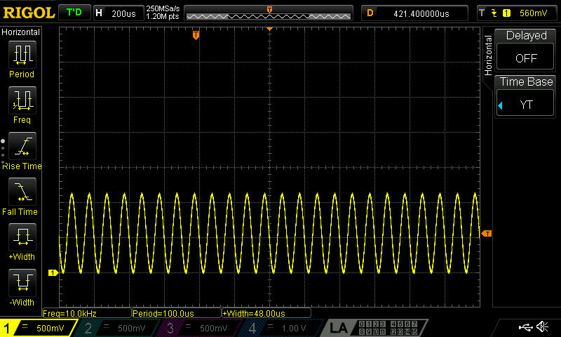
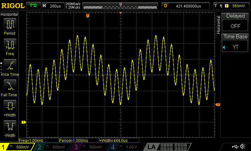
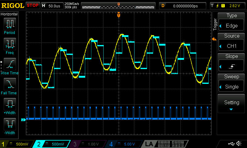
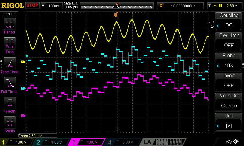
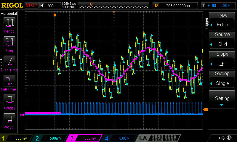
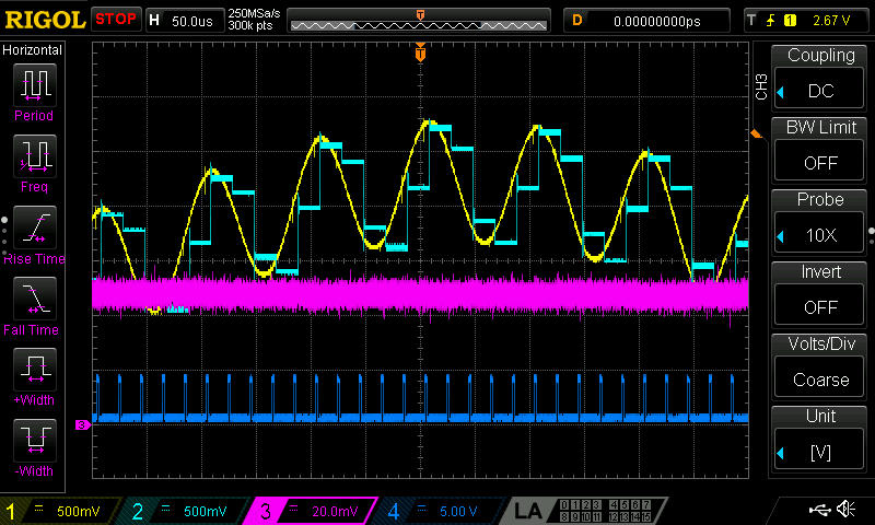
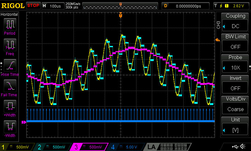
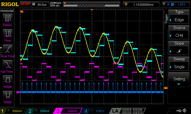
Channel 1 (Yellow) = 1kHz + 10kHz (2MHZ / 2MSPS) DAC signal and fed back to the ADC pin of the MCU by shorting wire
Channel 2 (Cyan) = ADC captured value sent to DAC (50ksps, kilosamples per sec)
Channel 3 (Pink) = Low / High Pass FIR / IIR filter output from FMAC
Channel 4 (Blue) = 50kHz ADC Sampling point (FMAC Interrupt)
- 1.) Generate 2 freq of sinewaves, one low freq. like 1kHz and high freq like 10-20kHz. These signals will be fed to FIR filter and will be applied a LPF (low pass filter) and HPF (high pass filter)
- 2.) Trigger the ADC and display the ADC data by DAC
- 3A.) Trigger the ADC and feed to FIR filter (FMAC) by DMA and apply either LPF and HPF and send the filtered data out to DAC
- 3B.) Feed data to FMAC manually (Polling), this is useful if data is not coming from ADC but from other devices like accelerometer, vibrations, gyro etc.
* NUCLEO-G474RE_2FreqSineGenerator 			= (Step process 1)  2 freq, 1kHz + 10kHz, waveform generator by DAC (DMA)
* NUCLEO-G474RE_2FreqSineGenerator_to_ADC_DAC		= (Step process 2)  2 freq DAC (DMA) to ADC (DMA) to DAC (DMA)
* NUCLEO-G474RE_2FreqSineGenerator_to_ADC_DAC-02	= (Step process 2)  2 freq DAC (DMA) to ADC (IT to Callback) to DAC (Inside ADC Callback)
* NUCLEO-G474RE_RealTime_FIR_FMAC			= (Step process 3A) 2 freq DAC (DMA) to ADC (DMA) to FMAC (DMA) to DAC (ADC IT)
* NUCLEO-G474RE_RealTime_FIR_Poll-to-IT-FMAC		= (Step process 3B) 2 freq DAC (DMA) to Simulated ADC (TIM6) to Polling (Append data) FMAC to DAC (ADC IT)
From previous project DAC by DMA, it is possible to generate sinewaves of two freqs.
- GPIOC6/8/11 is used for troubleshooting
-
Activate TIM6
-
Prescaler = 17-1
-
ARR = 5-1
-
TRGO Event = Update event
-
setup in main.c
 /*##- Enable TIM peripheral counter ######################################*/
 if(HAL_OK != HAL_TIM_Base_Start(&htim6))
 {
 	Error_Handler();
 }
-
Set DAC High Freq. = 160MHz
-
Trigger TIM6 Out Event
-
DMA Settings
- Mode = Circular
- Increment Adress = Memory
- Data width = Word
-
Do not Disable DMA IT!
-
add #include "waveforms.h"
-
add High freq to become 2 freq in main.c
MySine2000[cntr];
MySine2000[cntr] += 682;MySine200[cntr];for (uint16_t cntr = 0; cntr < MySine2000_SIZE; cntr++) { MySine2000[cntr] += 682; MySine2000[cntr] += MySine200[cntr % MySine200_SIZE]; } -
setup DAC3 in main.c
 /*##- Enable DAC Channel and associated DMA ##############################*/
 if(HAL_OK != HAL_DAC_Start_DMA(&hdac3, DAC_CHANNEL_1,
 			   (uint32_t*)MySine2000, MySine2000_SIZE, DAC_ALIGN_12B_R))
 {
 	/* Start DMA Error */
 	Error_Handler();
 }
-
Mode = Follower DAC3 output1, input P
-
Power Mode = High Speed
-
Setup OpAmp6 in main.c
 /*##- Start OPAMP    #####################################################*/
 /* Enable OPAMP */
 if(HAL_OK != HAL_OPAMP_Start(&hopamp6))
 {
 	Error_Handler();
 }
Step 2 use HRTIM Master to trigger ADC (and use DAC output to display ADC data for testing if triggered)
-
Setup Master HRTIM
-
ADC trigger1 on Master Period
-
Setup HRTIM Master in main.c
 if(HAL_OK != HAL_HRTIM_WaveformCounterStart(&hhrtim1, HRTIM_TIMERID_MASTER))
 {
 	Error_Handler();
 }
-
Setup 1 Regular Conversion mode
- External trigger by HRTIM trig 1 event (Master Period)
-
Add DMA
- Mode Circular @ Memory, data width Word
-
ADC_Settings
- DMA Continous Request = Enable
- Overrun behaviour = overwritten
-
NVIC
- Enable DMA global IT with Call handler
- Disable ADC1-2 Global IT
-
Add callback for Regular Conversion mode in main.c, later will be used for DAC1 output
HAL_ADC_ConvCpltCallback(ADC_HandleTypeDef *hadc) { /* Prevent unused argument(s) compilation warning */ UNUSED(hadc); /* NOTE : This function should not be modified. When the callback is needed, function HAL_ADC_ConvCpltCallback must be implemented in the user file. */ HAL_GPIO_TogglePin(GPIOC, GPIO_PIN_11); adc_data = HAL_ADC_GetValue(hadc); HAL_DAC_SetValue(&hdac4, DAC_CHANNEL_1, DAC_ALIGN_12B_R, adc_data); } -
Calibrate then enable ADC with DMA in main.c
 /* Perform an ADC automatic self-calibration and enable ADC */
 HAL_ADCEx_Calibration_Start(&hadc1, ADC_SINGLE_ENDED);

 /*##- Enable ADC Channel and associated DMA ##############################*/
 if(HAL_OK != HAL_ADC_Start_DMA(&hadc1, &adc_data, 1))
 {
 	/* Start DMA Error */
 	Error_Handler();
 }
-
Enable DAC4
-
Set DAC High Freq. = 160MHz
-
Do not set any Trigger, DAC will not output with this command HAL_DAC_SetValue
-
Enable DAC4 in main.c
 /*##- Enable DAC Channel ##############################*/
 if(HAL_OK != HAL_DAC_Start(&hdac4, DAC_CHANNEL_1))
 {
 	/* Start Error */
 	Error_Handler();
 }
-
Mode = Follower DAC3 output1, input P
-
Power Mode = High Speed
-
Setup OpAmp4 in main.c
 /*##- Start OPAMP    #####################################################*/
 /* Enable OPAMP */
 if(HAL_OK != HAL_OPAMP_Start(&hopamp4))
 {
 	Error_Handler();
 }
Insert FMAC in between ADC and DAC output so we can apply FIR filter
-
Enable FMAC
-
Enable IT
-
include fmac.h
-
add VT_FMAC_init(void)
/*## Configure the FMAC peripheral ###########################################*/ sFmacConfig.InputBaseAddress = INPUT_BUFFER_BASE; // COEFF_VECTOR_B_SIZE = COEFFICIENT_BUFFER_SIZE = 5 sFmacConfig.InputBufferSize = INPUT_BUFFER_SIZE; // COEFF_VECTOR_B_SIZE (5) + MEMORY_PARAMETER_D1 (1) sFmacConfig.InputThreshold = INPUT_THRESHOLD; // FMAC_THRESHOLD_1 = 0x00000000U sFmacConfig.CoeffBaseAddress = COEFFICIENT_BUFFER_BASE; // = 0 sFmacConfig.CoeffBufferSize = COEFFICIENT_BUFFER_SIZE; // = 5 sFmacConfig.OutputBaseAddress = OUTPUT_BUFFER_BASE; // COEFFICIENT_BUFFER_SIZE + INPUT_BUFFER_SIZE sFmacConfig.OutputBufferSize = OUTPUT_BUFFER_SIZE; // MEMORY_PARAMETER_D2 = 2 sFmacConfig.OutputThreshold = OUTPUT_THRESHOLD; // sFmacConfig.pCoeffA = NULL; // no A coeffs sFmacConfig.CoeffASize = 0; // no A coeffs sFmacConfig.pCoeffB = aFilterCoeffB; // sFmacConfig.CoeffBSize = COEFF_VECTOR_B_SIZE; // 5 sFmacConfig.Filter = FMAC_FUNC_CONVO_FIR; // sFmacConfig.InputAccess = FMAC_BUFFER_ACCESS_NONE; /*!< Buffer handled by an external IP (ADC for instance) */ sFmacConfig.OutputAccess = FMAC_BUFFER_ACCESS_IT;// /*!< Buffer accessed through interruptions */ sFmacConfig.Clip = FMAC_CLIP_ENABLED; // sFmacConfig.P = COEFF_VECTOR_B_SIZE; // 5 sFmacConfig.Q = FILTER_PARAM_Q_NOT_USED; // 0 sFmacConfig.R = GAIN; // if (HAL_FMAC_FilterConfig(&hfmac, &sFmacConfig) != HAL_OK) { /* Configuration Error */ Error_Handler(); } /*## Preload the input and output buffers ##################################*/ if (HAL_FMAC_FilterPreload(&hfmac, NULL, INPUT_BUFFER_SIZE, NULL, 0) != HAL_OK) { /* Configuration Error */ Error_Handler(); } /*## Start calculation of FIR filter in polling/IT mode ####################*/ if (HAL_FMAC_FilterStart(&hfmac,&Fmac_output,&ExpectedCalculatedOutputSize) != HAL_OK) { /* Processing Error */ Error_Handler(); } -
Edit FMAC IT
 void FMAC_IRQHandler(void)
 {
 	/* USER CODE BEGIN FMAC_IRQn 0 */

 	/* USER CODE END FMAC_IRQn 0 */
 	/* USER CODE BEGIN FMAC_IRQn 1 */

 	HAL_GPIO_TogglePin(GPIOC, GPIO_PIN_8);

 	uint32_t tmp;
 	tmp = READ_REG(hfmac.Instance->RDATA);
 	//  tmp = (tmp > 0x00007FFF ? 0 : tmp); // no need to clamp negative values
 	HAL_DAC_SetValue(&hdac1, DAC_CHANNEL_1, DAC_ALIGN_12B_R, tmp + 1000);

 	/* USER CODE END FMAC_IRQn 1 */
 }
-
Enable DAC1
-
Enable Output Buffer
-
Set DAC High Freq. = 160MHz
-
Do not set any Trigger, DAC will not output with this command HAL_DAC_SetValue
-
Enable DAC1 in main.c
 /*##- Enable DAC Channel ##############################*/
 if(HAL_OK != HAL_DAC_Start(&hdac1, DAC_CHANNEL_1))
 {
 	/* Start Error */
 	Error_Handler();
 }
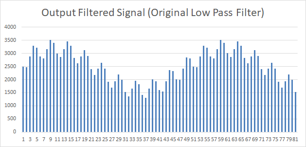
- 1kHz + 10kHz signal (CH1, Yellow) aquired by ADC and sent to DAC (CH2, Cyan). CH4 is ADC sampling points.
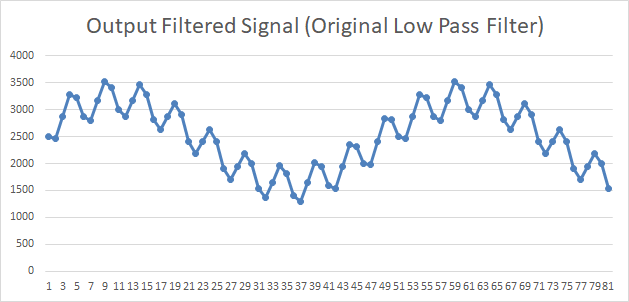
- ADC data printed out by MCU and imported to Excel for plotting
In line graph
In Bar graph
-
From original Coeffs used in previous FMAC study and analysis, the coeffs are
static int16_t aFilterCoeffB[COEFF_VECTOR_B_SIZE] = { 2212, 8848, 13272, 8848, 2212 }; -
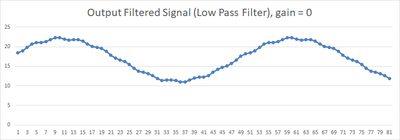
Calculated by MCU and output to DAC, with GAIN = 0
Verified in Excel and plotted
In line graph
In Bar Graph
-
Filtering is not good, need to update the coeffs to properly filter it, new Coffs
static int16_t aFilterCoeffB[] = { 5987, 6832, 7129, 6832, 5987 }; -
MCU output to DAC, with GAIN = 0
- Calculated by Excel
-
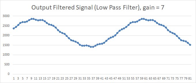
Very Low Pass Filter Coeffs
static int16_t aFilterCoeffB[] = { 70, 0, 127, 0, 70 }; -
MCU output to DAC, with GAIN = 0
- Calculated by Excel
- Change gain of 7 in FMAC, that is R = 7, 2^7 = 128. Excel Plot.
- MCU output
-
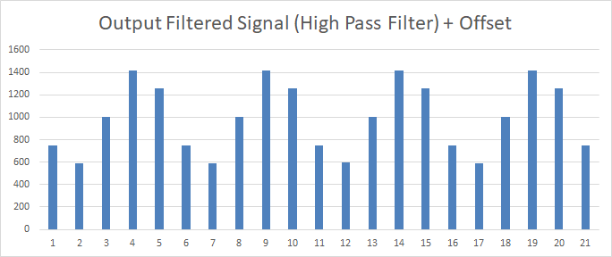
High Pass filter coeffs
static int16_t aFilterCoeffB[] = { -2570, -8318, 21777, -8318, -2570 }; -
Calculated thru Excel
- Offset is added because MCU DAC cannot generate negative voltages
- MCU DAC output plus offset
STM32F429I-DISC1_FIR_FFT_wth_Print Project
Use of FMAC for FIR Low Pass Filter
Online Sine Look Up Table Generator Calculator
Disclaimer: Updated Disclaimer
The projects posted here are for my Personal reference, learning and educational purposes only. The purpose of a certain project may be for testing a module and may be just a part of a whole project. It should not be used in a production or commercial environment. Any cause of injury and/or death is the sole responsibility of the user.
