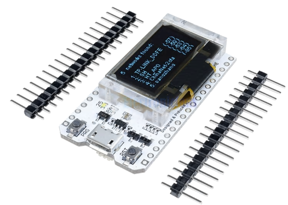
ESP32 code for my ESP32 Development board, using Arduino IDE. See table below.
ESP32 Development board called "WiFi Kit 32" Developer board from Heltec Automation with:
- Tensilica LX6 dual-core 32-bits processor, clocked at 240MHz, computing power up to 600DMIPS,
- Chip built-in 520 KB SRAM and Onboard 32MByte Flash
- Bluetooth: integrated dual-mode Bluetooth (traditional Bluetooth and BLE low power Bluetooth)
- Wifi: transceiver 802.11 b/g/N HT40(only PCB Antenna)
- SX1278 chip for LoRa remote modem, 433MHz frequency (measured open area communication distance 2.6Km).
- Onboard 0.96 Inch OLED Display with 128x64 pixels, Blue, SSD1306 chipset/driver
- lithium battery (lipo) charging circuit and interface
- CP2102 Module USB to serial chip
- Compatible with the Arduino development environment.
| Code | Description | Pins used |
|---|---|---|
| BasicStepperDriver | Drives a stepper motor, using DRV8825 | DIR on GPIO 1 |
| STEP on GPIO 23 | ||
| GetrChipID | Displays the unique internal chip id | not applicable |
| Gyro_and_StepperMotors | Uses a Gyro sensor to drive 2 stepper motors | Work in Progress! |
| - Gyro (MPU-9250) is connected via Wire1 | SDA on GPIO 21 | |
| SCL on GPIO 22 | ||
| INT on GPIO 2 | ||
| - Motor-1 | DIR on GPIO 1 | |
| STEP on GPIO 23 | ||
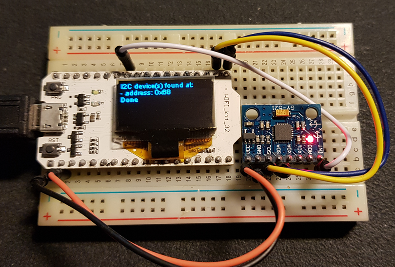
| I2C_Scanner_VibeSoft | Scans for I2C devices on 2nd I2C bus | SDA on GPIO 21 |
| Output on OLED display and serial port. | SCL on GPIO 22 | |
| Sensor_MPU6050 | Gyro Sensor, read X,Y and Z angles | SDA on GPIO 21 |
| SCL on GPIO 22 | ||
| INT on GPIO 2 | ||
| Sensor_MPU9250 | 9DoF sensor MPU-9250 | SDA on GPIO 21 |
| - 3-Axis accelerometer | SCL on GPIO 22 | |
| - 3-Axis gyroscope | INT on GPIO 2 | |
| - 3-Axis magnetometer | ||
| WIFI_KIT_32_VibeSoft | Wifi scanner with minor modifications | not applicable |
Additional documentation, used in the source code

