A collection of Symbolic Quick Error Detection + Symbolic Starting States demos on a variety of processor designs along with supplemental resources.
Further detailed information can be found in each processor design's directory. Setup and usage details can be found in the directory README.
-
steelcore_democontains a work-in-progress demo on steel -
ridecore_demo- contains a demo on ridecore -
vscale_democontaints a SQED + SSS demo on vscale
-
demo_templates/contains a directory and file structure template for use deploying on new designs -
utilitiescontains helpful scripts for parsing output data -
presentations/contains slides and graphics related to this work -
papers/contains published papers and drafts related to this work -
imagescontains figures and images related to this work
We detail how to deploy SQED + SSS on a new design below using the Questa toolchain step-by-step.
Most of the designer effort is spent in the following tasks:
- Specifying the ISA format for the
sqed-generatorand modifying the output as needed to work on your design - Wiring up the QED Module to the design
- Writing the formal tool directives and properties to properly constrain the design for useful analysis.
Please review the directory structure details in the demo_template/README.md.
You can directly use the template as the starting point for deploying on a new
design.
cp -r demo_template/ [DESIGN NAME]_demo/
You should copy the unaltered version of the source design files into your demo directory. Generally you will want to specify a certain commit hash as a snapshot of the design you are verifying to ensure repeatability.
Used the sqed-generator
to generate the proper files for the qed/ directory. Be sure to include
the design-independent QED files to place in the qed/ directory.
Please follow the instructions in the repo for properly specifying ISA format files and generating the required files.
Use patches.sh to copy the relevant files from the source files into
design/
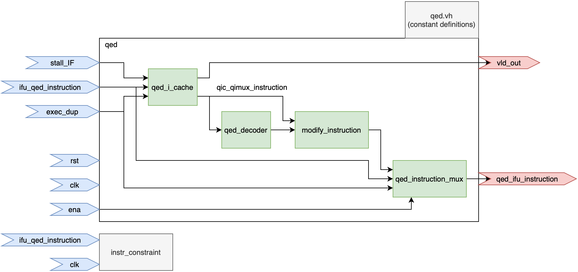
In the module which instantiates the top-level pipeline, edit the design to instantiate the QED module.
Generally this occurs in the following steps:
- Instantiate the
qedmodule in the pipeline - Disconnect the instruction signal at starting at the decode stage.
- Connect the
qed_ifu_instructionfrom the QED module to the decode stage - Ensure that
vld_outis properly handled in the design - Add logic for tracking the committed number of instructions in the design.
- Add logic for tracking when Symbolic-In-Flight (SIF) instructions have committed.
Our recommended workflow recommends copying the relevant design files from the
original design directory into the patches/ directory and edit them directly.
They can then use patch.sh to copy the file into design.
This allows a faster iteration loop than creating patch files.
After finishing the deployment, the designer can then create patch files
and apply them with the patch tool to better preserve transparency of
changes to the original design.
For example, in order to wire-up the QED module, we copy the top level pipeline
from the original design directory into the patches/ directory and
instantiate the QED module along with its supporting signals and logic in the
file. We then use the patch.sh script to simply cp this file into design
during make design. After we are sure wire-up is correct, we can export
the diffs as a patch file and only save the patch file in patches/wire-up/.
Wrap the top-level pipeline module in a design_top module in design_top.v
which exposes only a clock and reset for inputs. All other I/O into the
pipeline must be handled accordingly. If the design comes standalone as a
processor core only, without memory, a memory can be instantiated here and
connected properly.
In formal/directives.tcl, specify the following:
- Clock properties (frequency)
- Reset properties (typically tied to deasserted for SSS)
- Cutpoints
Cutpoints are signals which the formal tool treats as inputs over time.
Typically we should have two cutpoints for SQED + SSS -
the instruction signal and the exec_dup signal.
In formal/formal_spec.sv add proper assertions and constraints.
At a bare minimum, a QED consistency check and a valid instruction constraint
must be added. More properties may need to be added for more complex designs
to avoid spurious counterexamples.
In formal/formal_bind.sv, bind the proper signals in formal_spec.sv
to the design's signals. Typically this only involves binding the registers we
are checking for QED consistency to the register file.
