- Arduino Uno
- nRF24L01
- L298P Motor Shield
- 2
12vDC Motors - DC-DC Buck Converter
12v->9v - 2 High-Power Servos (not 9g, metal gears)
- Lasercut Chassis
- 3d Printed Wheels with Rubber bands
- Transfer Bearing Caster
- BUZZER =
4 - Servo1 =
A0 - Servo2 =
A1 - x1(Leftmost Dst Sensor) =
TBD - x2(Middle Dst Sensor) =
8 - x3(Rightmost Dst Sensor) =
TBD - Trigger(for activating dst sensors) =
7
- ENA =
5 - INA =
3 - ENB =
6 - INB =
2
- Ardiuno Uno
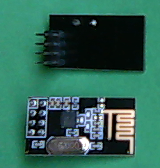
- nRF24L01
- Fundiuno Shield
9vBattery- SSD1306 128x64 OLED Screen i2c
- 3d Printed Transmitter Body
- Joystick X =
A0- Used for Motor and Scoop Control
- Joystick Y =
A1- Used for Motor and Scoop Tilt Control
- Joystick Button =
8- Hold to turn on fine control mode
- Button A =
2- Hold to use Joystick is to control Scoop
- Button B =
3- Not used currently
- Button C =
4- Not used currently
- Button D =
5- Hold with ButtonA to use old servo control method
- Button E =
6- Used to switch vScreen
- Button F =
7- Used to switch on/off Low Latency Mode
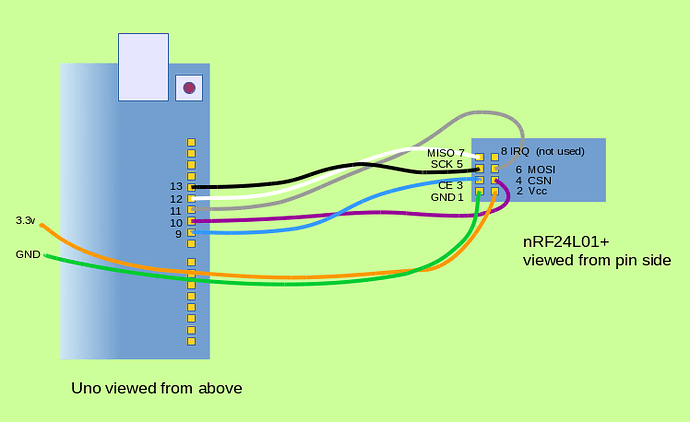
The shield is built to directly interface pins 10, 11, 12, 13 to the motor control ic for pwm control. However, those exact pins are the hardware SPI interface for the wireless module so we must use different motor control pins.
Since the arduino uno has hardware PWM on pins 3, 5, 6, 9, 10, 11 we can use these pins instead by bending the shield pins to the side so we can connect them manually to the arduino.
- nRF24
pin1-> ArduinoGnd - nRF24
pin2-> Arduino+3.3v. If you hook it up to+5vit will probably break. - nRF24
pin3-> ArduinoIOpin9 - nRF24
pin4-> ArduinoIOpin10 - nRF24
pin5-> ArduinoIOpin13 - nRF24
pin6-> ArduinoIOpin11 - nRF24
pin7-> ArduinoIOpin12 - nRF24
pin8is not required since we are not using interrupts (IRQs), leave this pin disconnected
The shield is built to directly interface pins 10, 11, 12, 13 to the motor control ic for pwm control. However, those exact pins are the hardware SPI interface for the wireless module so we must use different motor control pins.
Since the arduino uno has hardware PWM on pins 3, 5, 6, 9, 10, 11 we can use these pins instead by bending the shield pins to the side so we can connect them manually to the arduino.
IOpin2->IOpin12IOpin3->IOpin13IOpin5->IOpin11IOpin6->IOpin10
- We are using rechargeable power drill batteries. Get a 3D printed battery mount and terminal contacts from Mr. Mayer
- Solder stranded wire to two right angle terminal tabs.
- Insert the tabs into the 3D printed mount, be sure the red wire is on the + side and the black wire is on the - side.
- Mount the 3D printed mount on your robot, there are lots of mounting holes.
- Connect the power wires to the 2 positiong blue screw terminal block. The black wire goes into the GND terminal, the red wire goes into VMS.
- Note, the power entering here powers everything as long as the OPT jumper is installed on the Motor Shield. That jumper interconnects the motor power to the Arduino power.
- Value of
Joystick Xfrom-100to100 - Value of
Joystick Yfrom-100 to 100
- Value of
Button A - Value of
Button B - Value of
Button C - Value of
Button D - Value of
joyButton - Value of
llMode(from0-1,1is engaged)
motorAMotor A power percent (0-100)motorBMotor B power percent (0-100)x1Distance value for leftmost distance sensor (centimeters)x2Distance value for middle distance sensor (centimeters)x3Distance value for rightmost distance sensor (centimeters)scoopPosRotation of the scoop arms up/down (uses big servos attached to robot)scoopRotRotation of scoop bucket (uses tiny servos)- Whether doingLL is true
0-1(1is engaged)
