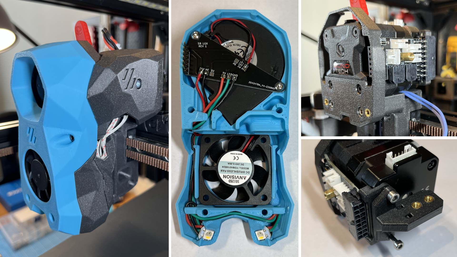
This mod is a custom 2-piece PCB design, as well as a few printed parts, to make the Bondtech LGX fully compatible with the Voron Stealthburner.
This mod is based on two existing mods, all credits go to them for the initial design :
- LGX Stealthburner Mount Remix by Symataris on Thingiverse (link here)
- Stealthburner toolhead PCB by Hartk1213 (link here)
I really like the 2-piece PCB design by Hartk, with which you just plug the stealthburner in the main board via a connector, without having to deal with cables from the fans and LEDs.
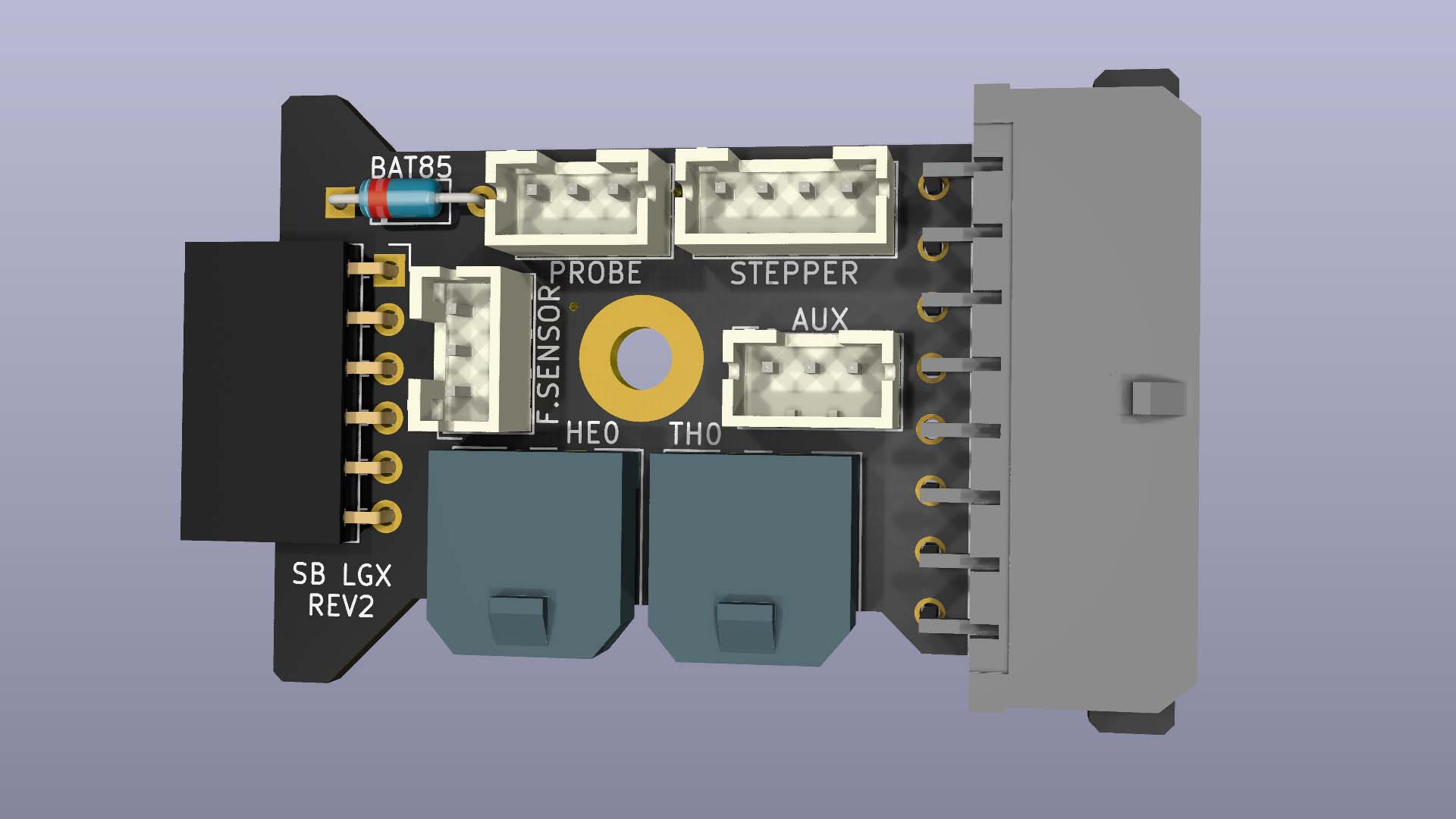
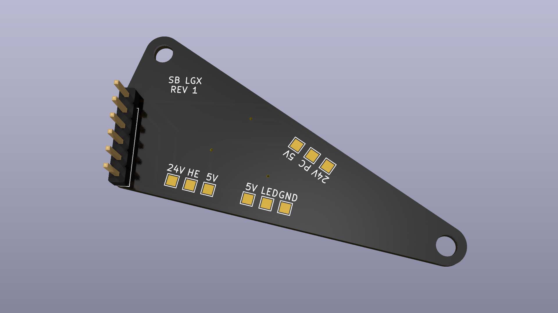
Instead of trying to source different parts from different mods and make them all compatible with each other, I decided to create this mod and design 2 new PCB's (one for the stealthburner, one on the LGX), as well as the printed parts required to have a fully completed Stealthburner + LGX, as cleanly assembled as possible.
Note: This BOM complements the original Stealthburner BOM. Only the extra compoments are included here. Items that are required for the original build are not included here. Refer to the stealthburner manual for a complete list of required components.
PCBs
- 1x Stealthburner side PCB (SB_PCB)
- 1x LGX side PCB (LGX_PCB)
Hardware
- 3x M3x6 Button head hex socket screws
- 1x 10mm standoff (female-female)
- 5x Heat set inserts (or 4 if using 2-hole cable chain)
- 1x M3x6 Socket head Cap Screws
- 2x M3x18 Socket head Cap Screws
- 2x M3x20 Socket head Cap Screws
- 2x M3x25 Socket head Cap Screws
- 2x M3x30 Socket head Cap Screws
- 2x M3x8 Flat head Screws (can be slightly longer, not critical)
Connectors & Electronics
- 1x Pin header, 6 pos, 2.54mm (Molex 22-28-4063)
- 1x Pin Socket, 6 pos, right angle through hole (Samtec SSW-106-02-G-S-RA)
- 1x Molex 43045-1600 (Board 16-pin receptacle)
- 1x Molex 43025-1600 (16-pin connector)
- 16x Molex 43030-0007 (contacts for wires)
- 2x Molex 43650-0200 (Hotend & Thermistor receptacles)
- 2x Molex 43645-0200 (Hotend & Thermistor connectors)
- 1x BAT85 diode (optional, if using probe only)
- 3x JST-PH 3-pin male & female
- 1x JST-PH 4-pin male & female
(Note: JST-PH connectors can be bought in assortment boxes on Amazon for example. I recommend this, as you would have multiple sizes in male/female in sufficient quantity for this and future projects, or should you need to recrimp a new cable for example)
Other
- 1x Small PTFE tube (2mm ID x 4mm OD) (length varies depending on your hotend. See assembly instructions).
- Small zipties
Two Gerber zip files are provided for ordering the PCB's (LGX_PCB_Gerber.zip and SB_PCB_Gerber.zip).
I recommend JLCPCB or PCBWay for ordering the PCBs. I've personally ordered from JLCPCB and the boards were very cheap and worked perfectly.
An example order configuration for JLCPCB can be found here.
An example order configuration for PCBWay can be found here.
Pay attention to the important settings (marked with an exclamation point) when ordering the PCB's!
The LGX PCB should be a 4-layer board of 1.6mm thickness. (on JLCPCB only, you have to specify which layer is which, see picture)
The SB PCB should be a 2-layer board of 1.6mm thickness.
Other parameters are personal preference, like the color of the board, or if you want lead-free HASL for example.
The following parts need to be (re)printed :
- Stealthburner_Body.stl (There are small differences to the original file. Some small cutouts for a better PCB fit and the PCB mounting points have been modified.)
- LGX_Mount.stl
- LGX_Rear_PCB_Support.stl
- Cover.stl
- Cable_Chain_Anchor_xHoles..stl (Chose either the 2 or 3-hole version depending on your cable chain)
Note: These instructions are a complement to the original Stealthburner assembly manual. Keep a copy of the original manual open in parallel to these instructions, as I will often refer to it.
- Solder the components on the LGX pcb as shown on the picture. Make sure the 6-pin socket lays nice and flat on the PCB and is soldered straight. This is important for correct connection with the stealthburner later on.
- If you're not using an inductive probe (for example Klicky or KlickyNG mod with microswitch), replace the BAT85 diode by a small piece of wire to short the pads. A leg from a donor component (LED or resistor for example) works well here.
- Install a 10mm standoff using an M3x6 button head screw. Make sure the screw head does not stick out more than 2mm from the PCB. Make sure no solder points stick out more than 2mm. (to avoid touching and potentially shorting on the LGX extruder motor later on)
- Solder a 6-pin header to the SB PCB. The pins should face up.
- Follow the original manual instructions to install the LED's and fans into the stealthburner body. Leave the cables hanging for now.
- Install the PCB into the SB body and fasten with 2 M3x6 button head screws. Warning: Do not overtighten as these screw into plastic.
- Make sure the screws do not stick out of the SB body, or there would be a clearance issue with the LGX. (That's the reason why button head screws are used here instead of socket head)
- Solder all the wires onto the PCB as shown on the picture below. Note: The red (positive) wire of both fans can be soldered to either 24V or 5V depending on the voltage of your fans.
- Follow the stealthburner manual to assemble the printhead. You can print either the CW1 or CW2 version of the printed parts.
- Install the PTFE tube into the hotend. The length of the tube will vary depending on your hotend. The tube should stick out 25mm from the top of the printed part.
- Install 2 heat set inserts into the LGX Mount as shown. Install 2 (or 3) heat set inserts into the cable chain anchor as shown.
- dissasemble the front part of your LGX extruder.
- On the backside, remove the 2 left screws.
- Slide the LGX_Mount onto the LGX extruder and fasten with 2 M3x20 on the bottom and two M3x27 (original screws from LGX) on the front.
- Slide the PCB into the LGX_Mount printed parts grooves until it is fully seated into place.
- Install the PCB rear support printed part. It should slide onto the PCB and insert into the holes of the extruder motor.
- Install the cable chain anchor and fasten everything together with 2 M3x25 screws.
- Now is a good time to make sure no solder points touch the LGX extruder motor.
- Follow the stealthburner manual to install the carriage and probe (or klicky).
- Fasten the LGX assembly onto the carriage with 2 M3x30 screws. Make sure the probe wires are routed correctly and are not pinched between the carriage and LGX.
- Slide the printhead from the bottom into the LGX assembly. Make sure it is fully inserted, flush with the LGX mount, and flush on the X-carriage.
- Slide the Stealthburner in place. Make sure the pins align correctly with the socket. It is recommended to first align and insert the pins, then slide the SB fully in place.
- Fasten the Stealthburner with 2 M3x18 screws on top, and 2 M3x50 screws on the bottom.
- Prepare a small cable for the extruder motor with JST-PH connectors as shown. Its length should be about 90mm.
- Install the extruder motor cable.
- Wire up the rest of the components, including the hotend, thermistor, probe or switch, etc
- Fasten the cable chain with 2 M3x8 flat head screws. Install a ziptie into the ziptie slot.
- Wire up and install the 16-pin connector. The wiring schematic is the same as the original Hartk PCB. The only difference is that the 14 and 2-pin connectors have been joined into a single 16-pin connector. The individual wires position is identical. See the wiring instructions here.
- Optionally, install a chamber thermistor. I've attached mine at the backside on the cable chain and routed the wires to the AUX connector on the PCB.
- Install the cover by sliding the backside over the M3 screws sticking out of the LGX, and then fasten on the side with 1 M3x6 Socket head Screw.
While I've manage to assemble everything on my printer, there may be issues I haven't thought of, mistakes on this page, or issues that will only arise after many hours of printing.
USE THIS MOD AT YOUR OWN RISK!
I'd appreciate any kind of feedback, good or bad.
If you encounter issues, please open an issue on this github page.


