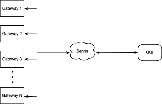
Several tags are located by an antenna array with 16 antenna elements as shown in the picture.
You will get information by *.json file and show the information on the interface according to requirements as follows.
- Upload time stamp, phase, rss, tag id
{
  	"atnid": ['gateway1','gateway2'],
    "atnpos": {'gateway1':[x,y],'gateway2':[x,y]},
    "time": us,
    "tagid": i,
    "phase": {'gateway1':[phase0, phase1,..., phase15],'gateway2':[phase0, phase1,..., phase15]},
    "rss": {'gateway1':[rss0, rss1, ..., rss15],'gateway2':[rss0, rss1, ..., rss15]}
    "spectrum": [[a0_0,a0_1,..a0_199],[a1_0,a1_1,...,a1_199], ..., [a199_0, a199_1, ..., a199_199]],
    "aoa": {'gateway1':[angle,radius],'gateway2':[angle,radius]}
    "pos": [x,y],
}
the python dictionary is converted to JSON data. Each element in the dictionary is as follows:
-
"time": usThe value of
"time"is an integer. It denotes the timestamp of the data. -
"tag": iThe value of
"tag"is an integer. It denotes the serial number of a tag, may be 1,2,3,4,....... -
"phase": [phase0, phase1,..., phase15]The value of
"phase"is an1-D arrayand the shape is (16, ). Each element in the array denotes the phase of one ANTENNA ELEMENT. The type of element isfloat. -
"rss": [rss0, rss1, ..., rss15]The value of
"rss"is an1-D arrayand the shape is (16, ). Each element in the array denotes the rss of one ANTENNA ELEMENT. The type of element isfloat. -
"spectrum": [[a0_0,a0_1,..a0_199],[a1_0,a1_1,...,a1_199], ..., [a199_0, a199_1, ..., a199_199]]The value of
"spectrum"is an2-D arrayand the shape is (200,200). The type of element isfloat. -
"pos": [x,y]The value of
"pos"is an1-D array.xdenotes the x-coordinate of the position.ydenotes the y-coordinate of the position.
Each JSON data will be saved as a separate file. The folder will be organized as follows:
data
  - t1.json
  - t2.json
  - t3.json
  .
  .
  .
- A web frontend. This web controls basic functions oon this server. For example, users can start an experiment via webpage by entering the experiment name. Also, Lists of experiments will be shown on the webpage and users can delete experiment records.
- Deploy localization algorithm. Data from gateways is not the information of the location. So a localization algorithm will be deployed on the server and then it will convert raw data to location information.
- Remote update/edit the config file of gateways. Users can edit and update config files of connetced gateways so that it is convinient for users to debug.
- Start/Stop the gateways. Users can start/stop gateways.
- Add logs/figures of a specific experiment. Via the frontend of the server, users are able to upload some logs and images to a specific experiment record. For instance, a image of the experiment scene could be uploaded to the record.
- After start the gateways, save data in the MongoDB. Aftering starting gateways, the server will save all data sent by gateways in a MongoDB. And when the GUI reqiures location data, the server would send data in the MongoDB.
- Update the ground truth file(.csv) offline to the MongoDB. For each experiment record, there would be a csv file which contains groudtruth data of this experiment. And users can upload this file to each experiment on the webpage.
- Log in/out. Users need username and password to log in to operate experiment records, like deleting an experiment record in the MongoDB.
- Query. On the frontend webpage, users can search/add/remove the experiment records after login.
- List all
- Replay(queue)
- Tag filter: choose which tag related to the information to show on the chart
- Antenna element filter: choose which antenna element related to the information to show on the chart
keep the latest K (e.g. 2000) numbers of latest phase values of the corresponding one antenna element (or multiple antenna elements) and plotting them in time series.
- Tag filter: choose which tag related to the information to show on the chart
16 squares indicate 16 different antenna elements in the array, with red/green color indicates bad or good RSS status (with color bar) respectively and show the value of RSS on these colorful squares.
- Tag filter: choose which tag related to the information to show on the chart
Scatter the value of spatial spectrum on the corresponding plane based on grids. Plot at 1 time/second.
- Tag filter: choose which tag related to the information to show on the chart
- Position Range: adjust the
xlimandylimof the localization plot figure.
Plot position on a 2D/3D grid keeping the latest M points (e.g. M=100). Position are (x,y) lists.
The explanations and pictures are meant to give you straightforward description for the different 4 parts of information, and it would be great if you add your own creativity and ideas to make it fancy and eye-catching.

