Social Robot Otto Project for UC Davis IEEE Organization
Over the course of the COVID-19 pandemic, many individuals (myself included) felt quite isolated from our friends and loved ones. While it was obviously possible for individuals to interact with one another virtually due to the countless digital peripherals that we have at our disposal, it's often important for humans to have phyiscal interaction. This comes in many forms, such as pets; but there's also potential for us to interact with synthetic buddies. Enter social robots like Otto.
Otto is a small friendly social robot that was developed by Nestworks based largely on the designs and programs of BoB the Biped https://www.instructables.com/BoB-the-BiPed/. The design is entirely open-source and was therefore a good candidate for a personal project due to the wealth of documentation available.
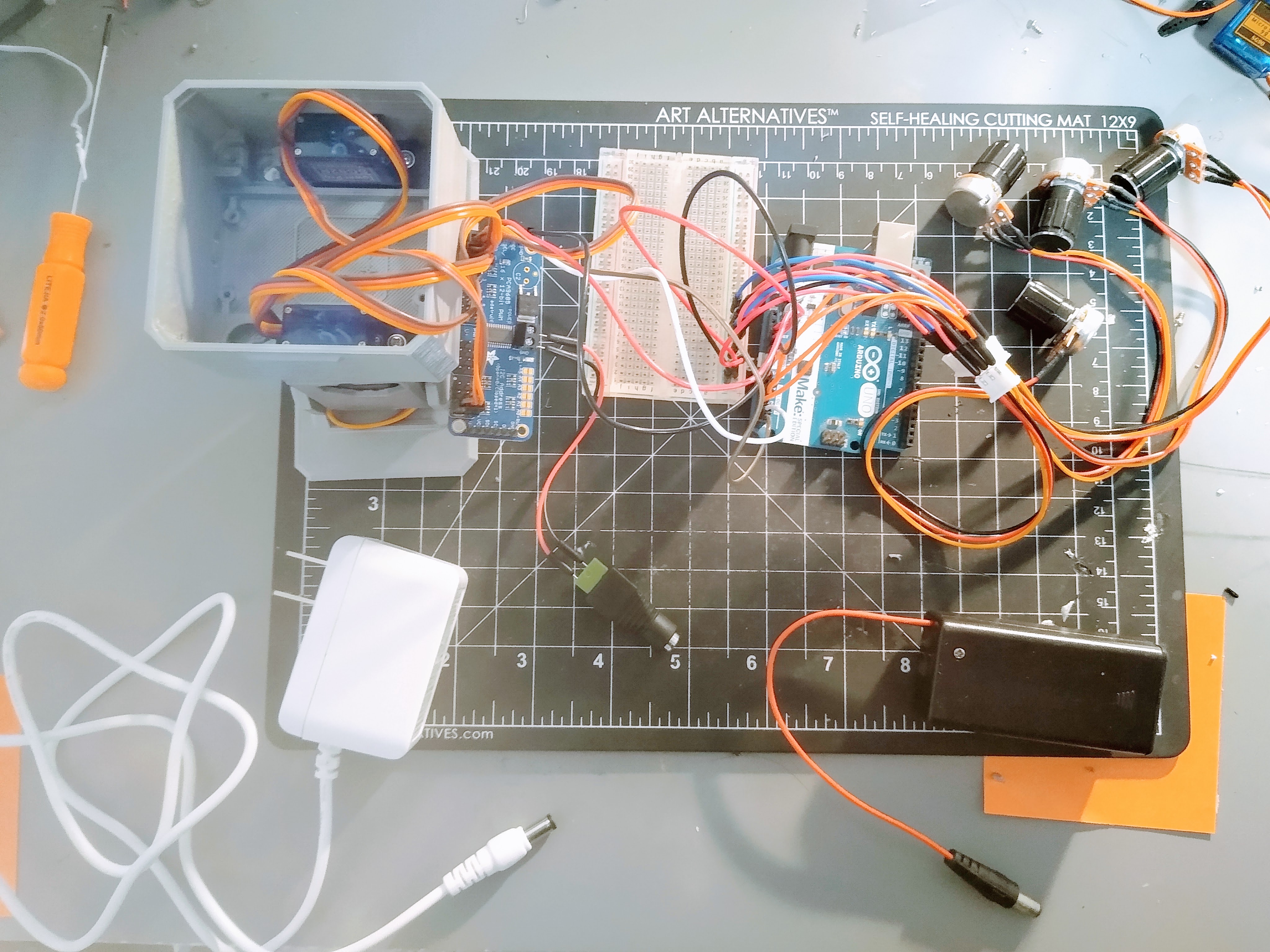 In order to construct my own version of Otto, I used the following supplies:
- Arduino Uno
- Adafruit 16-Channel PWM Servo Driver
- 4x 4k Ohm Variable Potentiometers
- 4x SG92R Tower Pro Servo Motors
- 9V DC Female Header Connector
Some of these components were common hobbyist parts that I had lying around but several of the key components, most notably the Adafruit PWM Driver, were generously provided by the UC Davis IEEE Chapter for usuage.
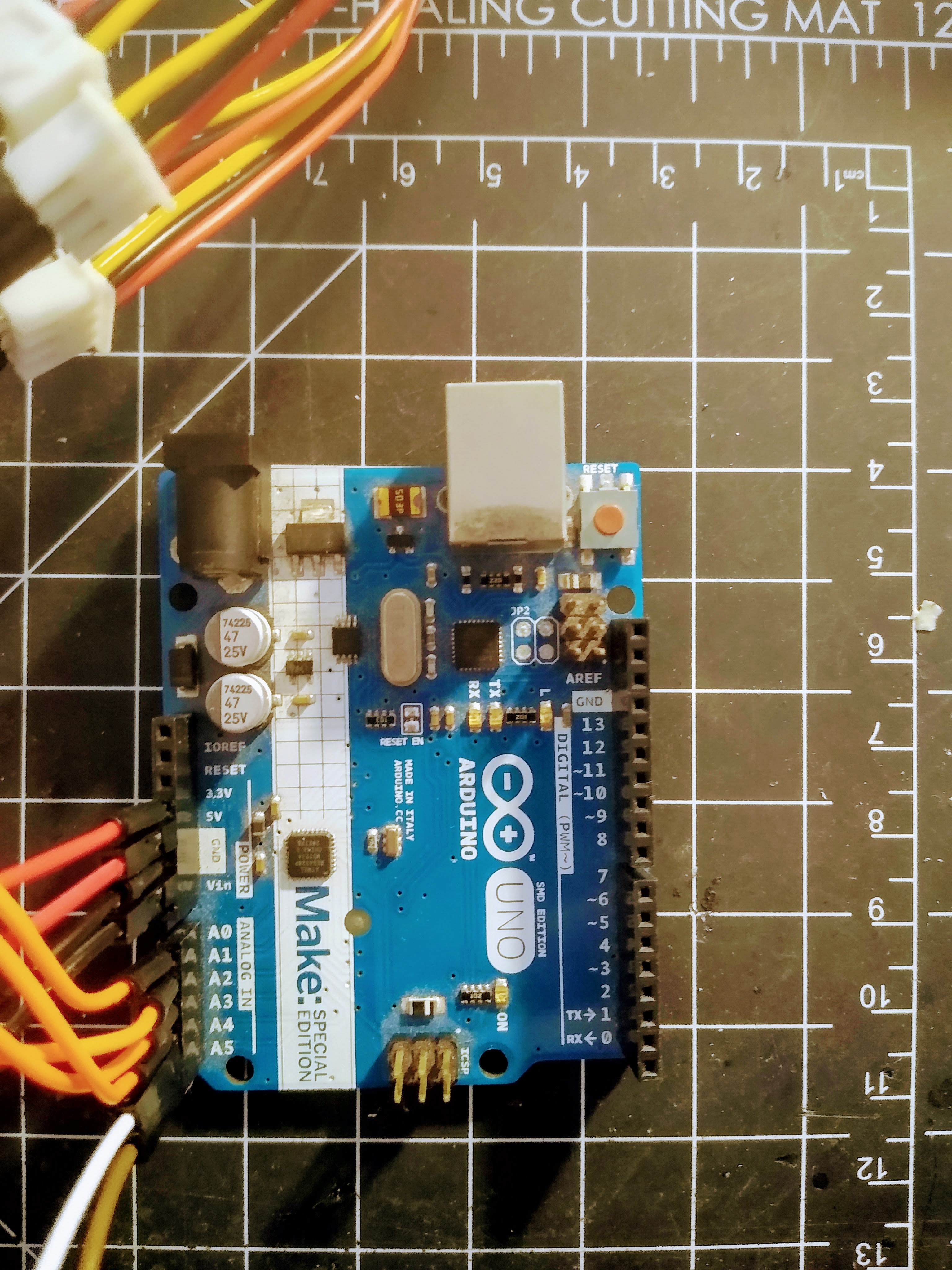
Here are some of the parts up close!
The Arduino Uno is an ATmega32P open-source microcontroller that has 14 digital I/O pins, 5 analog pins, 2 interrupt pins, and a 16MHz resonator timer that allows for users to perform AVR interrupts. It's a versatile MCU that forms the "brains" of the robot by handling user input and passing along relevant signals for processing in the servo driver.
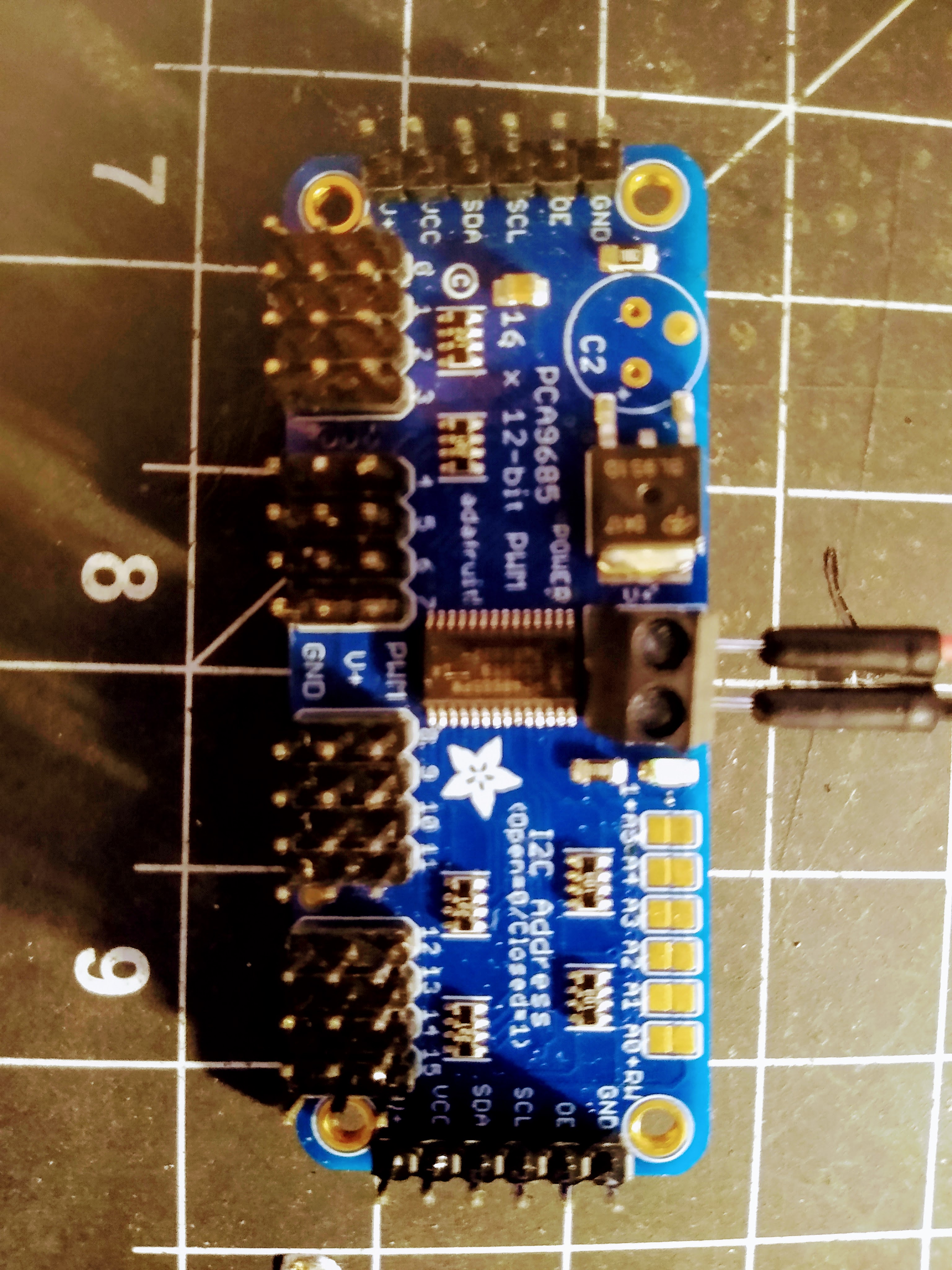
Next we have the Adafruit 16-Channel PWM Servo Driver. This component is probably the next most crucial element in the entire robot since without it, the servo motors would not be able to move properly. See, Servo motors are essentially small DC motors with a small integrated encoder built into the entire assembly. In other words, the complex circutry that has to keep track of the DC motor's position, velocity, and voltage is all built into the servo motor. All we need to provide to the servo motor is a signal. This signal is called the Pulse Width Modulation signal; and is a square wave. The width of the square wave is known as the duty cycle and by varying the duty cycle, we can change the PWM signal as well.

Another close-up shot of the 16-Channel Servo Driver. Nifty little thing.
We also need our means of controlling the servo motors directly. So to address that, I quickly wired four variable resistor potentiometers into the Arduino's analog input pins so we can read signals from the potentiometers.
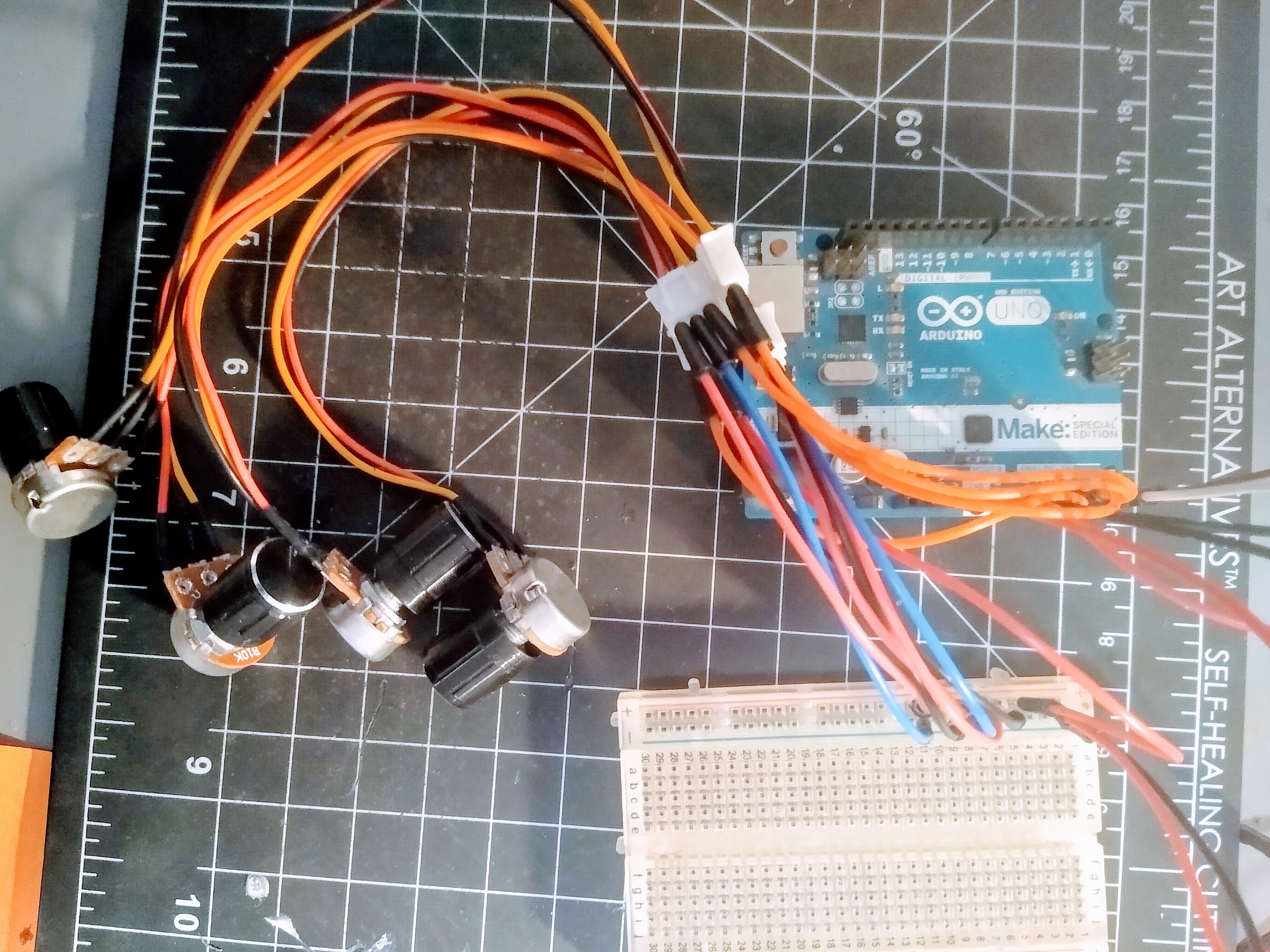
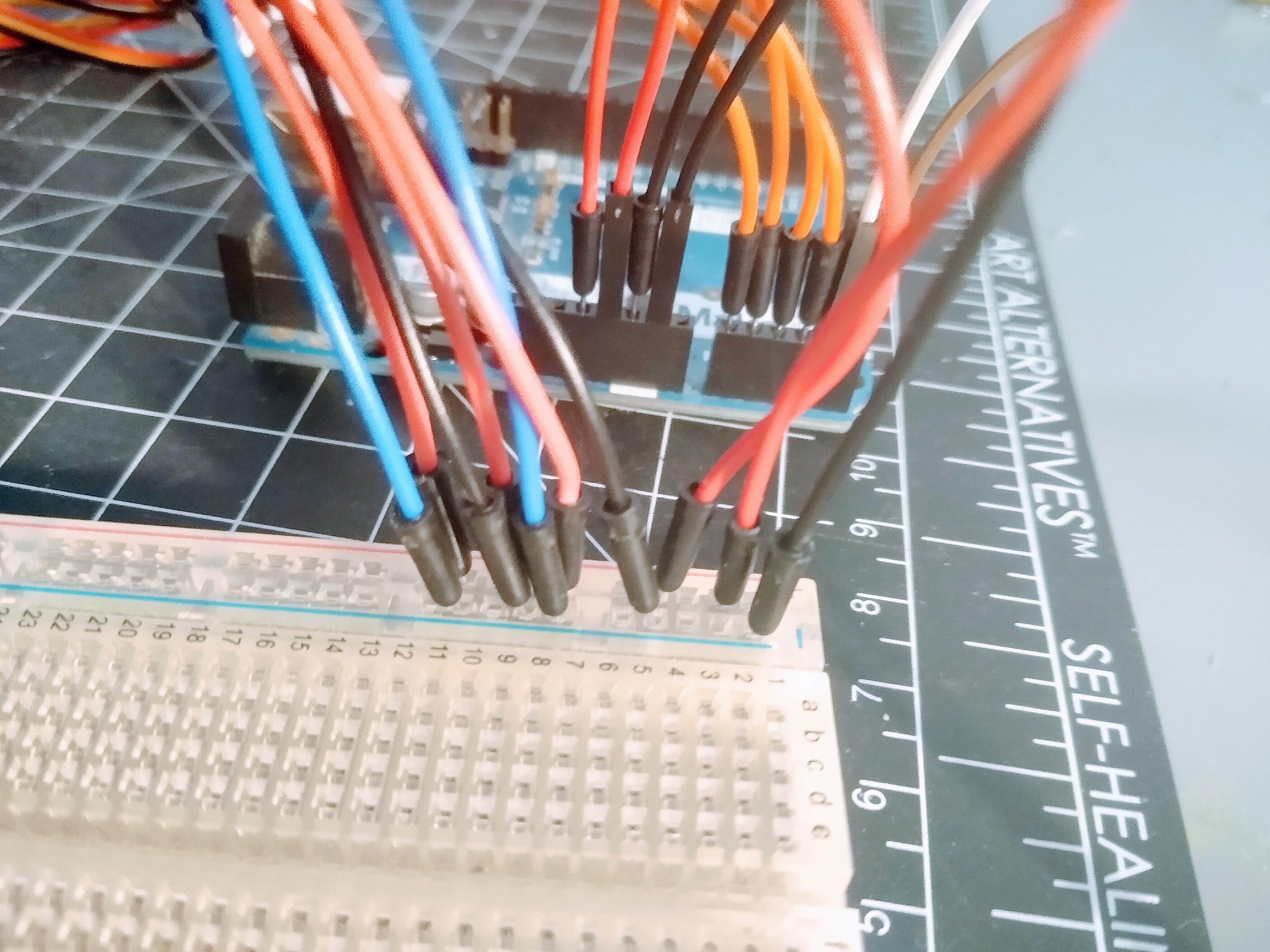
Some up-close shots of the connections between the potentiometer signal pins to the microcontroller:
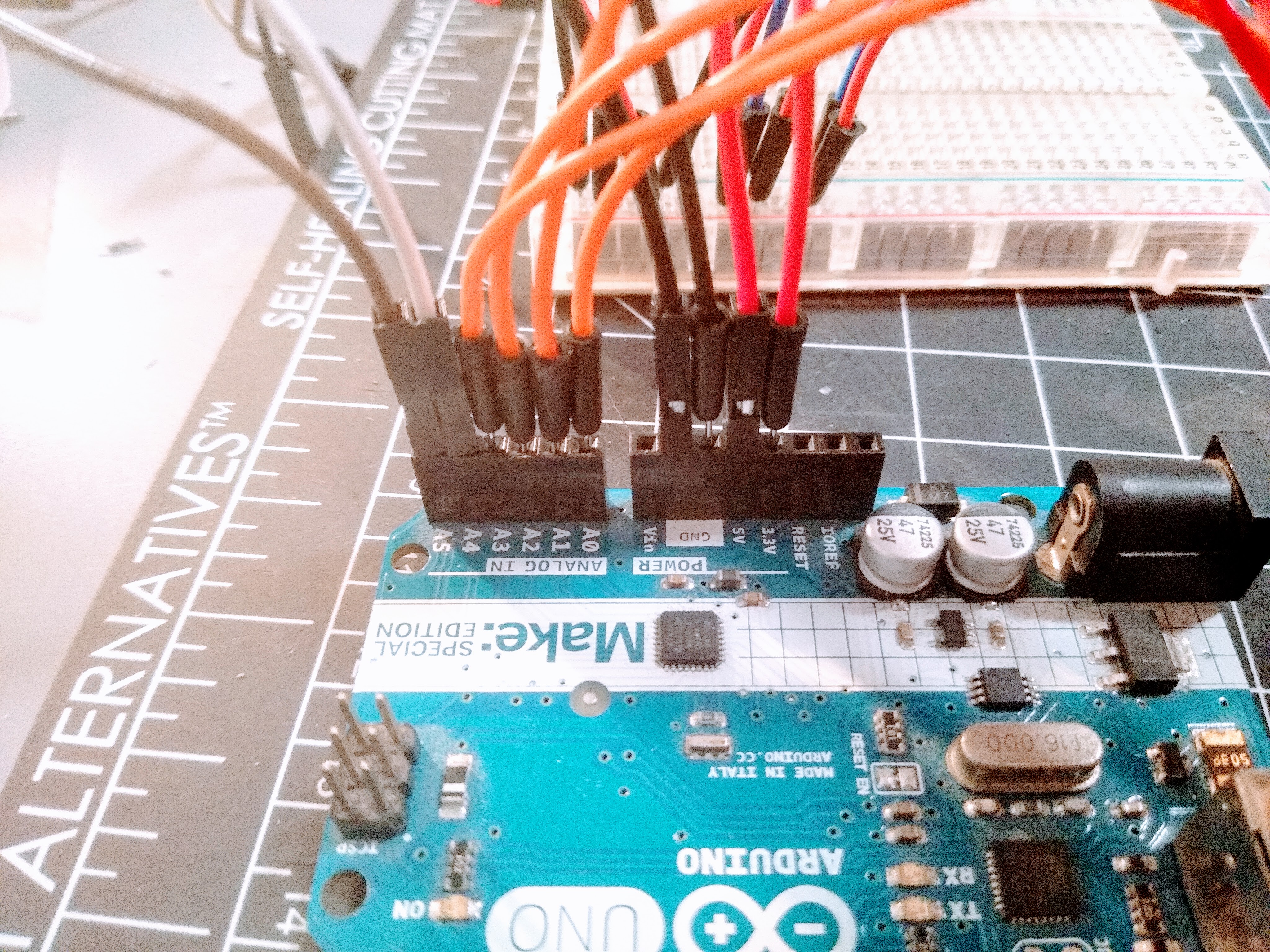
Since there are only two pins on the Arduino for GRN and 5V, we can just connect the potentiometer pins for power in parallel on the breadboard and then loop that back to the microcontroller's power pins.
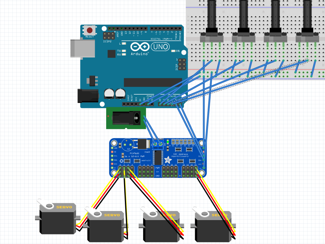
Of course, we wouldn't be able to do anything meaningful if none of the electrical components were actually connected. The good news for us is that these off-the-shelf parts are so common and straightforward that wiring them together is a piece of cake. The main points of interest worth bearing in mind are in making sure that the 16-Channel Adafruit Servo driver is correctly connected to Analog Pins A5 and A4 on the microcontroller. Meanwhile, we can allocate analog pins A0 through A3 to our four potentiometers. It's important that we draw the discinction between analog and digital pins real quick. Digital pins are just meant to handle binary inputs and outputs. They are either ON or OFF. Meanwhile, since the variable potentiometers are giving us a range of values, we need the analog pins to handle many different types of numbers.
Here's a Fritzing diagram of our overall setup.
I'd say the trickiest part of designing and implementing any sort of robot is the computer programming. In the case of programming my own Otto robot, I know that I wanted the user to be able to interact with the robot through the potentiometer sensors. There was also the case of physical limitations with the allowable range of motion for each of the servo joints. Since we don't have any physical sensors like limit switches that can automatically stop Otto drom dislocating itself, we need to methodically program into the robot a set of limiting values. There was also the issue of telling the servos to move. Luckily for us, Adafruit provides a library of open-source functions and objects that make acuation of the joints as simple as giving a PWM signal and calling the appropriate function.
#include <Wire.h>
#include <Adafruit_PWMServoDriver.h>

Adafruit_PWMServoDriver driver = Adafruit_PWMServoDriver();

#define SERVOMIN 150
#define SERVOMAX 600
#define USMIN 600
#define USMAX 2400
#define SERVO_FREQ 50

//servo counter pins
uint8_t RightHip = 0;
uint8_t LeftHip = 1;
uint8_t RightFoot = 2;
uint8_t LeftFoot = 15;

//pot pins
int pot1 = A0;
int pot2 = A1;
int pot3 = A2;
int pot4 = A3;

const int NUM_POTS = 4;

//starting servo positions
int RHIP_START_POS = 260;
int RHIP_MAX = 300;
int RHIP_MIN = 200;

int LHIP_START_POS = 340;
int LHIP_MAX = 400;
int LHIP_MIN = 275;

int RFOOT_START_POS = 350;
int RFOOT_MAX = 400;
int RFOOT_MIN = 250;

int LFOOT_START_POS = 320;
int LFOOT_MAX = 400;
int LFOOT_MIN = 250;

int currMap;
int reading, num;
int readings[NUM_POTS], servoPos[NUM_POTS], newPos[NUM_POTS], lastPos[NUM_POTS];
Fine tuning Otto was a bigger hassle than I had originally realized. See, just telling a servo to move to a new position creates jerky (sometimes dangerous) and unsightly behavior that doesn't look good at all from the robot. In order to implement smoothing, I implemented a series of loops that check if new joint angles are desired from the potentiometer readings. The new desired positions are mapped and updated from the potentiometer signal (0-1024) to the servo PWM positions (0-255). We can then use a combination of delay() calls within our loops in order to actuate and move Otto's servos into the correct positions.
<
void readPot(void) {
  //int curr;
  reading = analogRead(pot1);
  readings[0] = min(reading, 100);
  reading = analogRead(pot2);
  readings[1] = min(reading, 100);
  reading = analogRead(pot3);
  readings[2] = min(reading, 100);
  reading = analogRead(pot4);
  readings[3] = min(reading, 100);

  //curr = reading;
  //return curr;
}

void mapServo(int pos[]) {

  //int mappings[4];
  servoPos[0] = map(pos[0], 0, 200, RHIP_MIN, RHIP_MAX);
  servoPos[1] = map(pos[1], 0, 200, LHIP_MIN, LHIP_MAX);
  servoPos[2] = map(pos[2], 0, 200, RFOOT_MIN, RFOOT_MAX);
  servoPos[3] = map(pos[3], 0, 200, LFOOT_MIN, LFOOT_MAX);

  //return mappings;
}

void setup() {
  // put your setup code here, to run once:
  Serial.begin(9600);
  Serial.println("INITIALIZE START ROBOT");

  driver.begin();
  driver.setOscillatorFrequency(27000000);
  driver.setPWMFreq(SERVO_FREQ);

  delay(10);

  uint8_t pulselen = 0;
  int average = ((SERVOMAX + SERVOMIN) / 2);

  driver.setPWM(0, 0, RHIP_START_POS);
  delay(500);
  driver.setPWM(1, 0, LHIP_START_POS);
  delay(500);
  driver.setPWM(2, 0, RFOOT_START_POS);
  delay(500);
  driver.setPWM(15, 0, LFOOT_START_POS);
  delay(500);

  //  for (uint16_t pulselen = 200; pulselen < 350; pulselen++) {
  //    driver.setPWM(2, 0, pulselen);
  //    delay(10);
  //  }

  delay(500);

  //POTENTIOMETER TEST DATA HERE
  pinMode(pot1, INPUT);
  readPot();
  mapServo(readings);

  for(int n = 0; n < 4; n++){
    lastPos[n] = servoPos[n];
  }

}
Again, our main loop gets a little crowded due to the fact that we're simultaneously attempting to track all four potentiometers at the same time as well as update the four servos accordingly. However, it's easiest to perform all of this by storing these values in a single integer array data structure rather than creating a bunch of variables of the same data type and wasting memory-space on the microcontroller itself.
void loop() {
  // put your main code here, to run repeatedly:
  //Serial.print("DRIVING");

  readPot();
  mapServo(readings);
  //servoPos = mapServo(readings);
  delay(200);

  for (int k = 0; k < NUM_POTS; k++) {
    Serial.print("POT POS: "); Serial.println(readings[k]);
    Serial.print("SERVO POS: "); Serial.println(servoPos[k]);
    if (servoPos[k] - lastPos[k] > 0) {
      for (uint16_t pulselen = lastPos[k]; pulselen < servoPos[k]; pulselen++) {
        driver.setPWM(k, 0, pulselen);
        delay(10);
      }
    }
    else if (servoPos[k] - lastPos[k] < 0) {
      for (uint16_t pulselen = lastPos[k]; pulselen > servoPos[k]; pulselen--) {
        driver.setPWM(k, 0, pulselen);
        delay(10);
      }
    }
  }

  for(int n = 0; n < 4; n++){
    lastPos[n] = servoPos[n];
  }
}
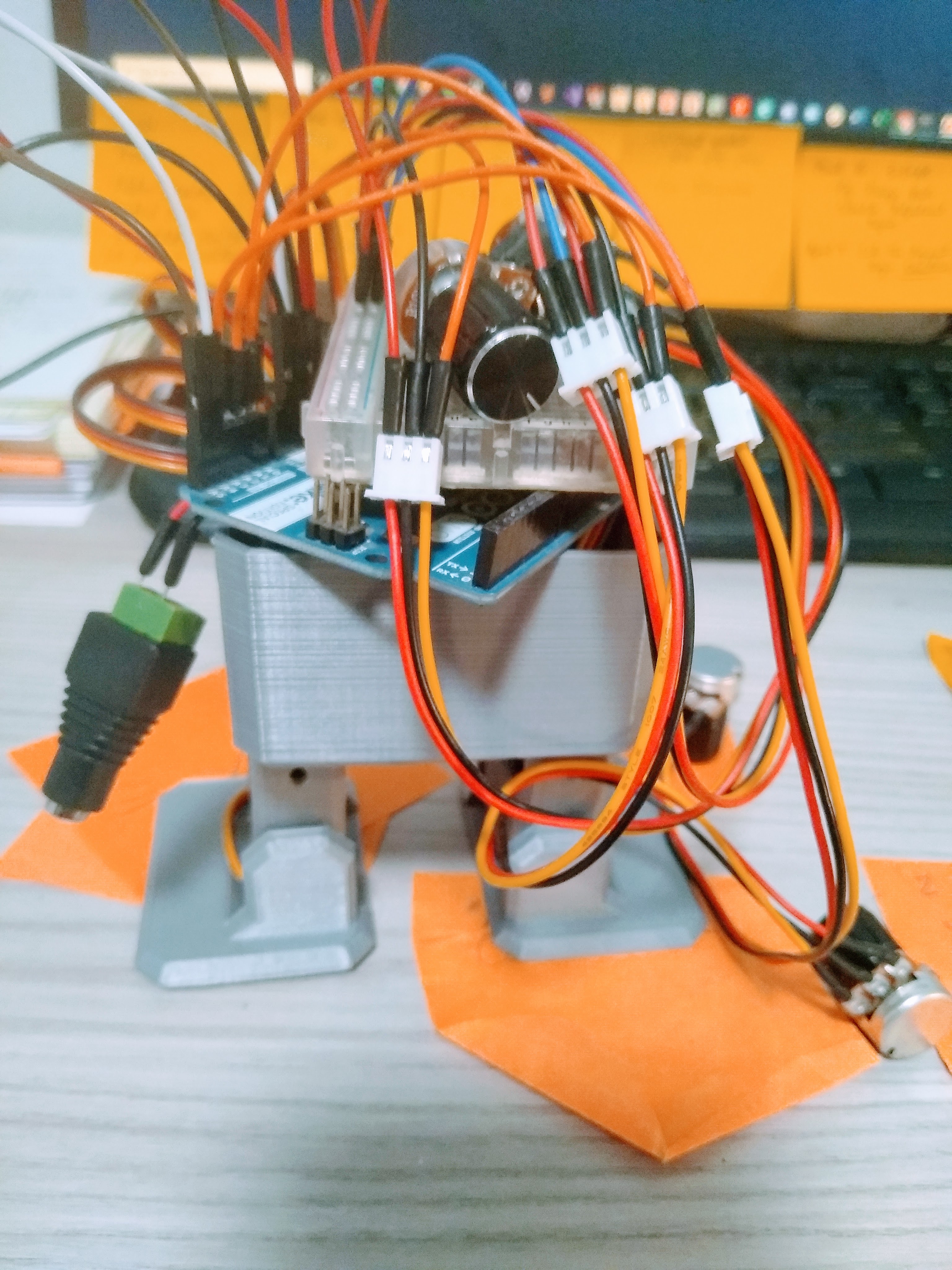
In the end...it sort of can dance and listen to user input! This was my first ever attempt at using servo motors and the Adafruit driver to attempt at making a bipedal walking robot, but so far it's been a very successful learning adventure. There are definitely still many bugs (ahem features) that I'd like to address as well as a few more sensors that I'd like to add. I also think that it'd be great to try and create a custom PCB board for handling additional analog sensors due to overcrowing of jumper cables around the microcontroller's ports. Ideally, something sort of like a microcontroller shield that fits over the board but also integrates the servo driver seamlessely would be fantastic. All in all, it's been a great project. I love robotics and putting together large complicated projects so let's see what the future of Otto brings.

I'd like to thank the UC Davis IEEE Chapter for their generous support and time in helping me every step of the way. Specifically, I'd like to acknowledge Varsha Senthil, Anelise Cho, and Devon Liu for their expertise and support. As someone who is still quite inexperienced and weak in electronics, your resources and advice put me in my paces towards making this little robot possible! Thank you!