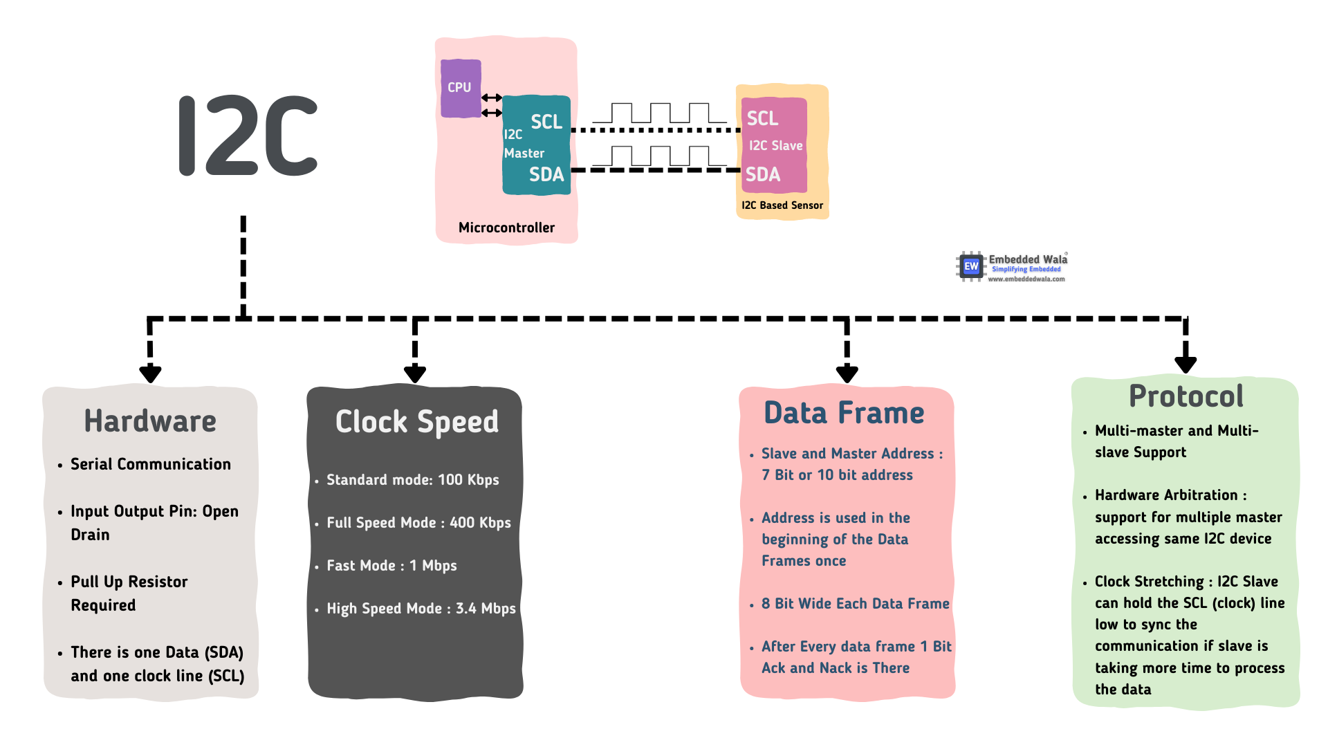
I2C stands for Inter-Integrated circuit. It can also be referred to as IIC or I2C. I2C Protocol is a serial communication protocol, and it is widely used for short-distance communication. It provides simple and robust communication between the Peripheral device and the microcontroller.
I2C Protocol consists of two wires SDA and SCL which is bidirectional synchronous serial bus communication. Thus, I2C Protocol takes two wires for communication which also translates to low cost and this low cost has made I2C Protocol the most commonly used Serial Bus across most applications including IoT, consumer electronics, automotive, aerospace, and industrial equipment.
I2C combines the best features of SPI and UARTs. With I2C, you can connect multiple slaves to a single master (like SPI) and you can have multiple masters controlling single, or multiple slaves. This is really useful when you want to have more than one microcontroller logging data to a single memory card or displaying text to a single LCD.
The Verilog implementation of the I2C RTL design comprises three fundamental modules: Master, Slave, and the I2C top-level module, which functions as the Register Interface (RIF) unit.
There are three main speed modes of I2C:
Standard Mode (up to 100 kbit/s) Full Speed Mode (up to 400 kbit/s) Fast Mode (up to 1 Mbit/s) High-Speed Mode (up to 3.4 Mbit/s)
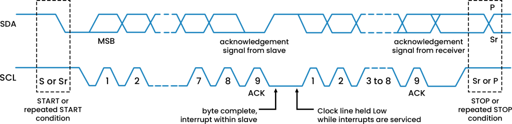
An I2C data frame consists of a Start Bit, a device address, a read/write bit, data bytes, acknowledge bit and Stop Bit.

I2C starts with a start condition, which is a sequence of signals that indicates the beginning of a communication cycle. The start condition is a high to low transition on the SDA line while the SCL line is high. After the start condition, the slave device's address is sent over the SDA line. I2C supports two addressing modes: 7-bit addressing and 10-bit addressing. In 7-bit addressing, each device is assigned a unique 7-bit address.
The master device sends the slave address in the first byte after the start condition, and the eighth bit of the byte is used to indicate if the master wants to write to or read from the slave device. In 10-bit addressing, each device is assigned a unique 10-bit address. The 10-bit addressing mode is used when a large number of devices need to be connected to the I2C bus, and the 7-bit addressing mode does not provide enough address space.

Once the slave address is received, the master device can send or receive data from the slave device.
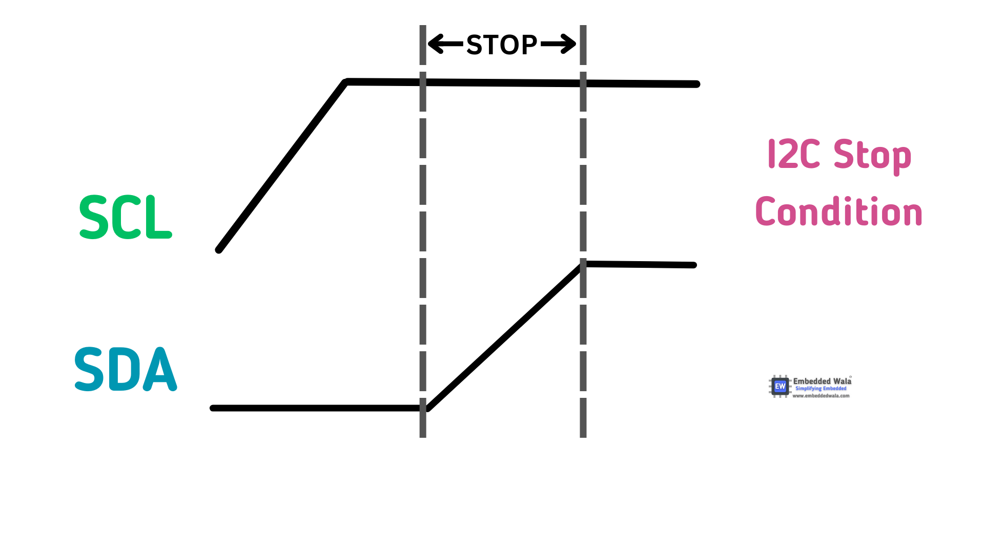
The stop condition is a sequence of signals that indicates the end of a communication cycle. The stop condition is a low to high transition on the SDA line while the SCL line is high. The stop condition is used to release the SDA and SCL lines and to signal the end of the communication cycle.
This repository also includes a simulation testbench (I2C_master_tb.v) to assist you in verifying the functionality of the I2C_master_tb module. You can use this testbench with Verilog simulation tools like GTKWave to observe the module's operation.
Ensure you have a Verilog simulation tool installed.
Compile the I2C_master.v and I2C_master_tb.v files.
Run the simulation, and monitor the waveforms to observe the I2C module's behavior.
Clone the project
git clone https://github.com/ZAIN-ALI-02/SPIGo to the project directory
cd I2CInstall dependencies
  install vscode
  install GTKWave
install icarus verilogTo run tests, run the following command
  iverilog -o I2C_master_tb.vvp I2C_master_tb.v
  vvp I2C_master_tb.vvp
GTKWave I2C_master_tb.vcdContributions are always welcome, suggestions, and issue reports. Feel free to create pull requests or open issues to help improve this I2C implementation. Together, we can make it even better!
This project is open-source and available under the MIT License. You are free to use, modify, and distribute this code as long as you comply with the terms of the license.