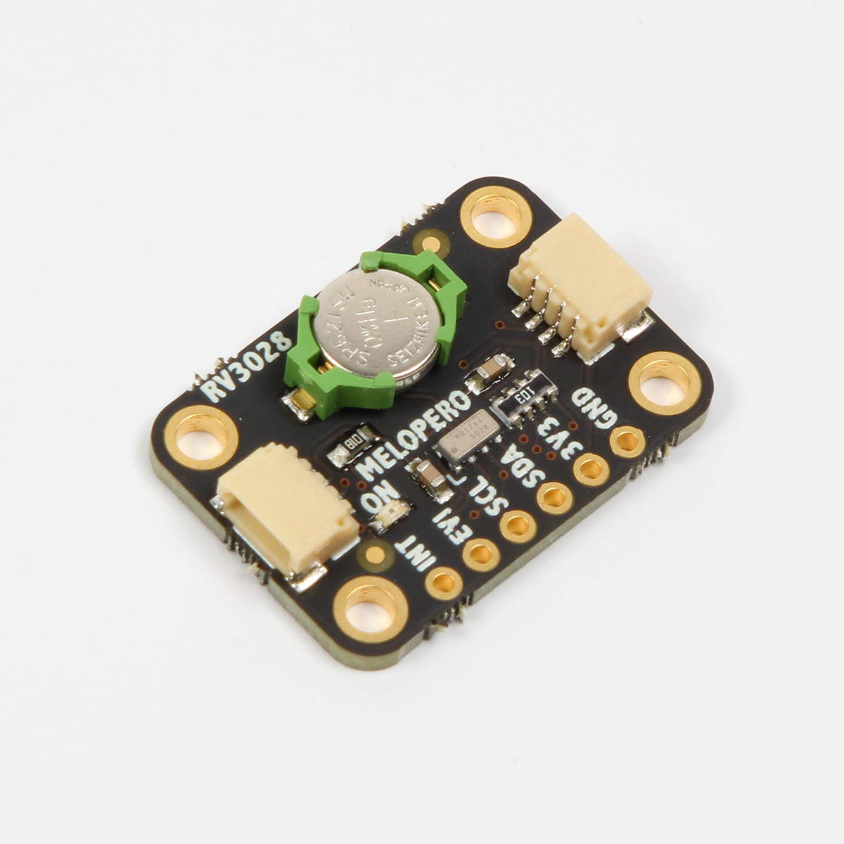
A library for interfacing the Melopero RV-3028 Extreme Low Power RTC module breakout with an Arduino board.
If you were looking for the Raspberry Pi Python3 library click HERE
| Melopero RV-3028 | Description |
|---|---|
| 3V3 | Input power pin. Apply 3.3V to this pin |
| SCL | I2C Serial CLock pin |
| SDA | I2C Serial DAta pin |
| GND | Ground pin |
| EVI | External Event Input(INPUT), pulled high (see schematics for more details) (this pin is not supported in our library) |
| INT | Interrupt Output, active LOW, pulled-high (see schematics for more details) |
You will need:
You can find a description of the pins of your specific Arudino board on the official Arduino websiteHERE
The RV-3028 communicates over I2C:
| Melopero RV-3028 | Arduino |
|---|---|
| 3V3 | 3.3V |
| SCL | SCL |
| SDA | SDA |
| GND | GND |
| INT | any available Digital pin |
This library can be installed directly from the Library manager of the Arduino IDE.
Open the Arduino IDE, select Sketch-->Include Library-->Manage Libraries.
Type "melopero rv3028", select the library and click on "Install".
The installation will include some examples, available under File-->Examples-->Melopero RV3028.
First you need to import the library and create the device object:
#include "Melopero_RV3028.h"

Melopero_RV3028 rtc;
Then you have to initialize the device inside the setup function:
...

void setup(){
    ...
    rtc.initDevice();
}
The initDevice function configures the Wire library needed to communicate with the sensor and performs all the required reset/initialization functions.
You can set the time with the setTime function:
rtc.setTime(year, month, weekday, date, hour, minute, second);
// Note: the time is always set in 24h format (even if you are using the 12 hour format)
// Note: month value ranges from 1 (Jan) to 12 (Dec)
// Note: date value ranges from 1 to 31
Note: Thanks to the battery of the sensor you don't have to set the time each time you power up the sensor.
To read the time you can use the following functions:
uint8_t second = sensor.getSecond();
uint8_t minute = sensor.getMinute();
uint8_t hour = sensor.getHour();
// if you are using the 12h format
bool pm = sensor.isPM();

uint8_t weekday = sensor.getWeekday();
uint8_t date = sensor.getDate();
uint8_t month = sensor.getMonth();
uint16_t year = sensor.getYear();

uint32_t unixtime = sensor.getUnixTime();If you want there is the option to use the 12h format for the time output:
sensor.set24HourMode(); // Set the device to use the 24 hour format
sensor.set12HourMode(); // Set the device to use the 12 hour format
bool is12hMode = is12HourMode(); // returns true if the device is in 12 hour mode
bool pm = isPM(); // if using the 12 hour mode returns true if it is PMYou can set alarms, timers and periodic time updates that may trigger an interrupt.
The alarm can be set to a combination of minutes, hours and date/weekday. Depending on the combination the period between an interrupt and the next one changes.
rtc.isDateModeForAlarm(); // returns true if the alarm is using the date instead of the weekday
rtc.setDateModeForAlarm(flag); // if true set the alarm to use the date else set the alarm to use the weekday
rtc.enableAlarm(uint8_t weekdayOrDate, uint8_t hour, uint8_t minute, bool weekdayOrDateAlarmEnabled, bool hourAlarmEnabled, bool minuteAlarmEnabled, bool generateInterrupt); // enables the alarm with the given parameters
rtc.disableAlarm(); //disables the alarm| weekdayOrDateAlarmEnabled | hourAlarmEnabled | minuteAlarmEnabled | effect |
|---|---|---|---|
| false | false | false | alarm disabled |
| false | false | true | when minutes match (once per hours) |
| false | true | false | When hours match (once per day) |
| false | true | true | When hours and minutes match (once per day) |
| true | false | false | When weekday/date match (once per weekday/date) |
| true | false | true | When minutes and weekday/date match (once per hour per weekday/date) |
| true | true | false | When hours and weekday/date match (once per weekday/date) |
| true | true | true | When minutes, hours and weekday/date match (once per weekday/date) |
The timer can be set to a number of ticks, the frequency of a tick can be selected.
/* Available frequencies
 * TimerClockFrequency::Hz4096 4096 ticks per second
 * TimerClockFrequency::Hz64 64 ticks per second
 * TimerClockFrequency::Hz1 1 tick per second
 * TimerClockFrequency::Hz1_60 1 tick per minute
*/

rtc.enablePeriodicTimer(uint16_t ticks, TimerClockFrequency freq, bool repeat = true, bool generateInterrupt = true);
rtc.disablePeriodicTimer();The sensor can trigger an interrupt every second or minute. To use this feature you can use the following functions :
//everySecond: if True the periodic time update triggers every second. If False it triggers every minute.
rtc.enablePeriodicTimeUpdate(bool everySecond, bool generateInterrupt);
rtc.disablePeriodicTimeUpdate();There are 43 Bytes of non-volatile User EEPROM, addresses from 0x00 to 0x2A.
Before using the eeprom the device must be set up accordingly:
// The automatic refresh function must be disabled.
// When you want to use the eeprom you have to call
// (once) the following method:
rtc.useEEPROM(bool disableRefresh = true);
To read and write to the eeprom registers you can use the following functions:
uint8_t reg_value = rtc.readEEPROMRegister(uint8_t registerAddress); // read
rtc.writeEEPROMRegister(uint8_t registerAddress, uint8_t value); // write
You can check if the eeprom is busy with this function:
rtc.isEEPROMBusy();The following function can be used to read and write to ram registers. In particular the device has two free ram bytes that can be used for any purpose.
uint8_t read_value = rtc.readFromRegister(uint8_t registerAddress);
rtc.writeToRegister(uint8_t registerAddress, uint8_t value);
rtc.writeToRegisters(uint8_t startAddress, uint8_t *values, uint8_t length);
rtc.andOrRegister(uint8_t registerAddress, uint8_t andValue, uint8_t orValue);

// The address of the two available bytes are:
uint8_t address1 = USER_RAM1_ADDRESS;
uint8_t address2 = USER_RAM2_ADDRESS;