During my work term at Lumotune I worked with developed LCD drivers and wanted to try a completely different type of display that I would be able to make on my own so I looked into making a RGB display. Just like the LED cube, multiplexing and persistence of vision were key techniques required. I used PWM drivers (TLC5940) to drive the specific values to the RGB LEDs in each column and shift registers (CD4094B) to switch between the rows. This is the first personal project dealing with complex IC so an online tutorial and base TLC5940 code from Kevin Darrah was used and expanded on: https://www.youtube.com/watch?v=FehBLNHMlfo
This code was used instead of existing libraries to understand lower level programming and in depth use of TLC5940.
- Original design was for 32 columns. This was reduced to 16 columns due to lack of RGB LEDs. The other sections have been updated to take this change into account.
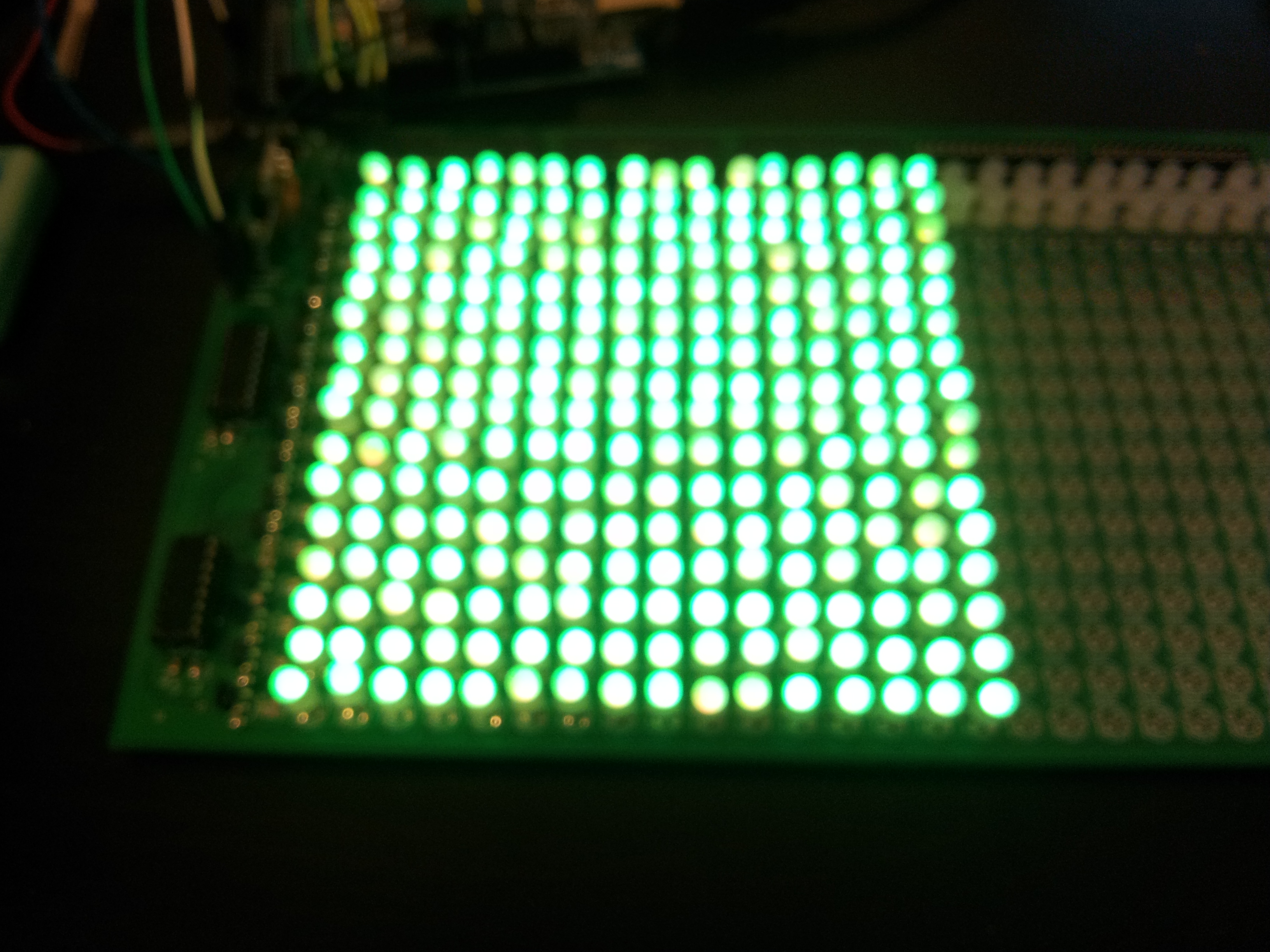
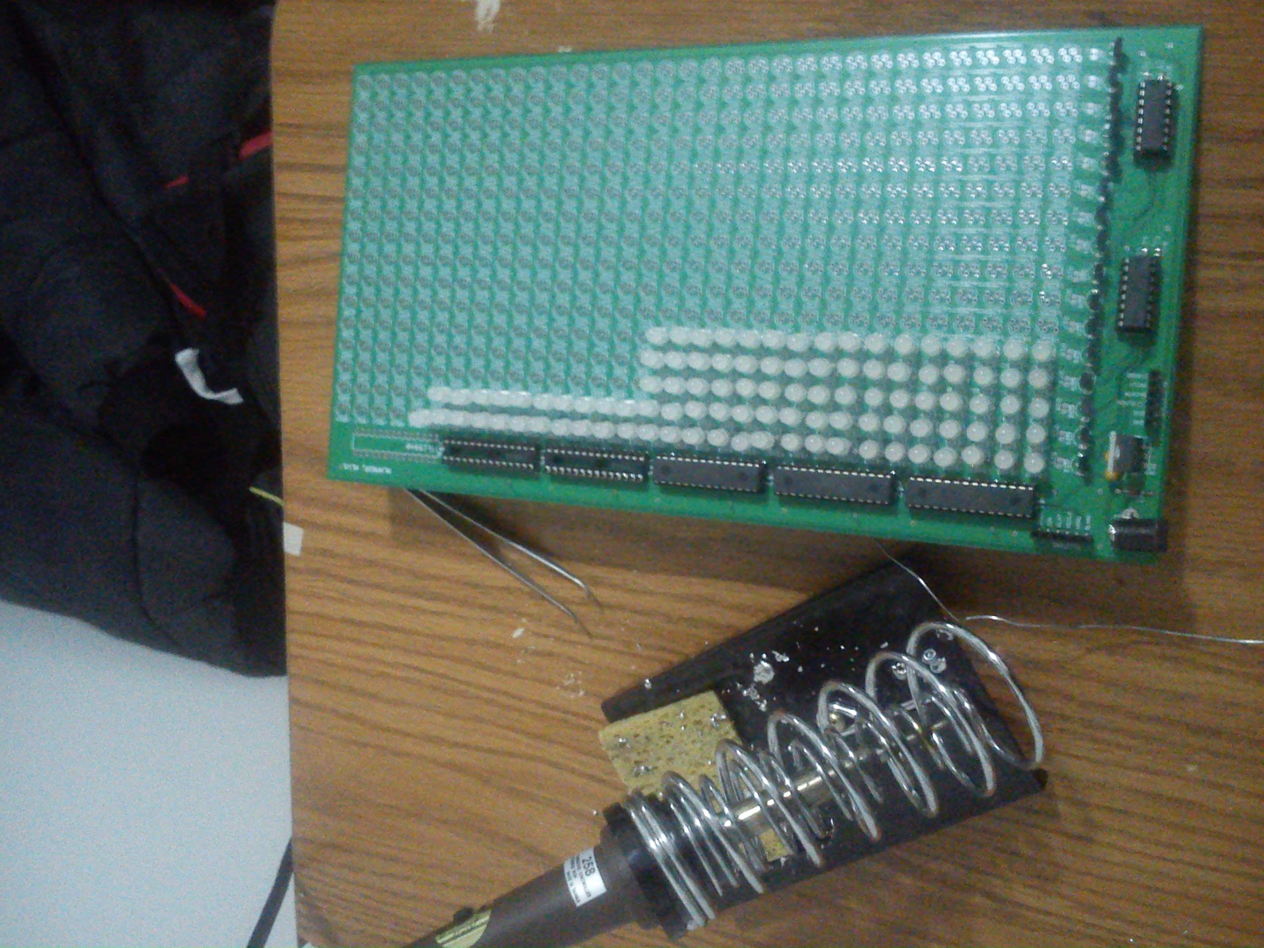
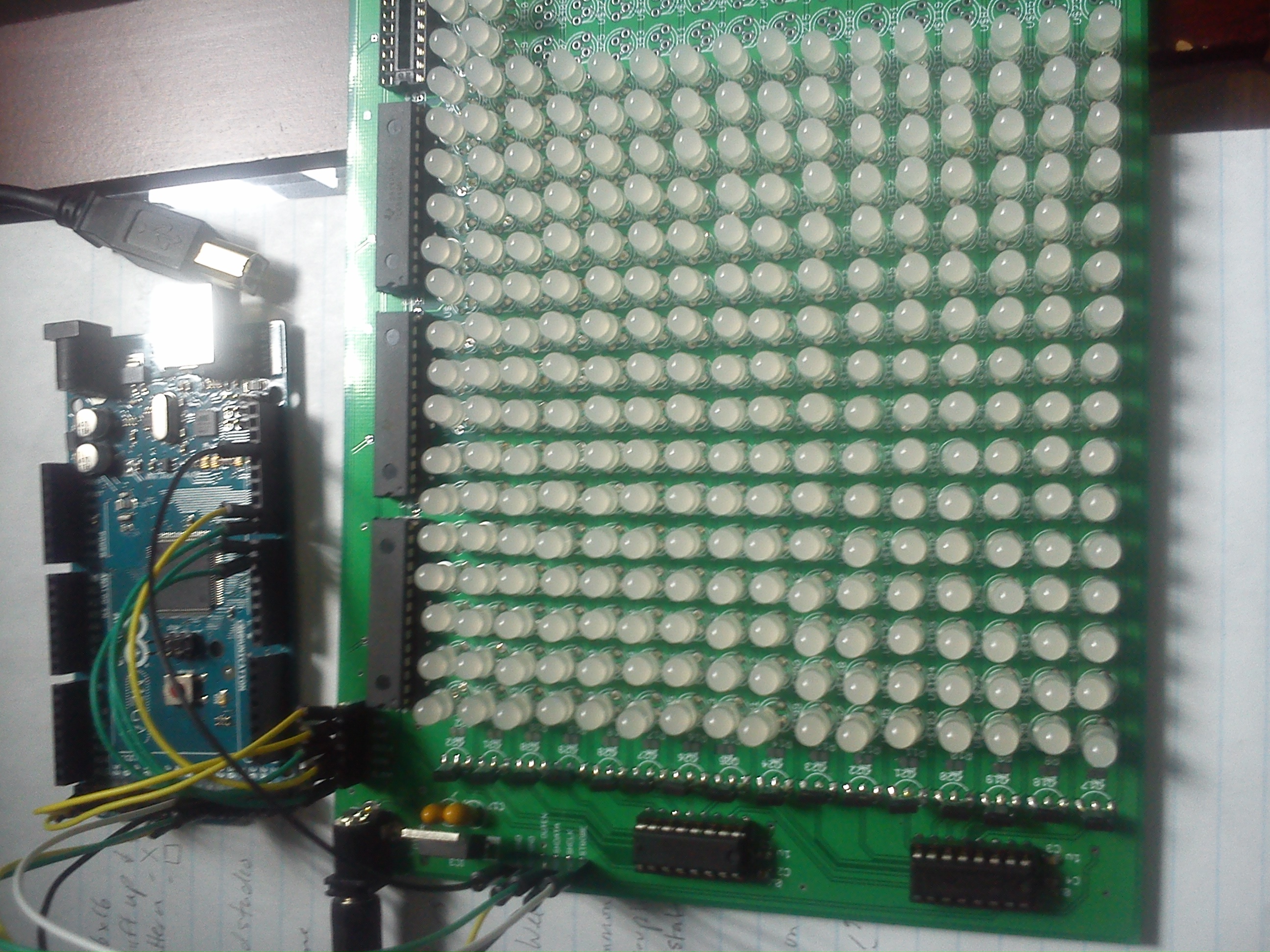
Here is an image of the 16x16 RGB Display:
Click below for a video of the display:
https://youtu.be/2PrOFA3ZqBM
(Material list has been updated)
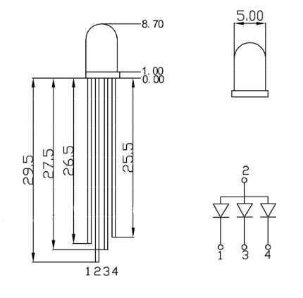
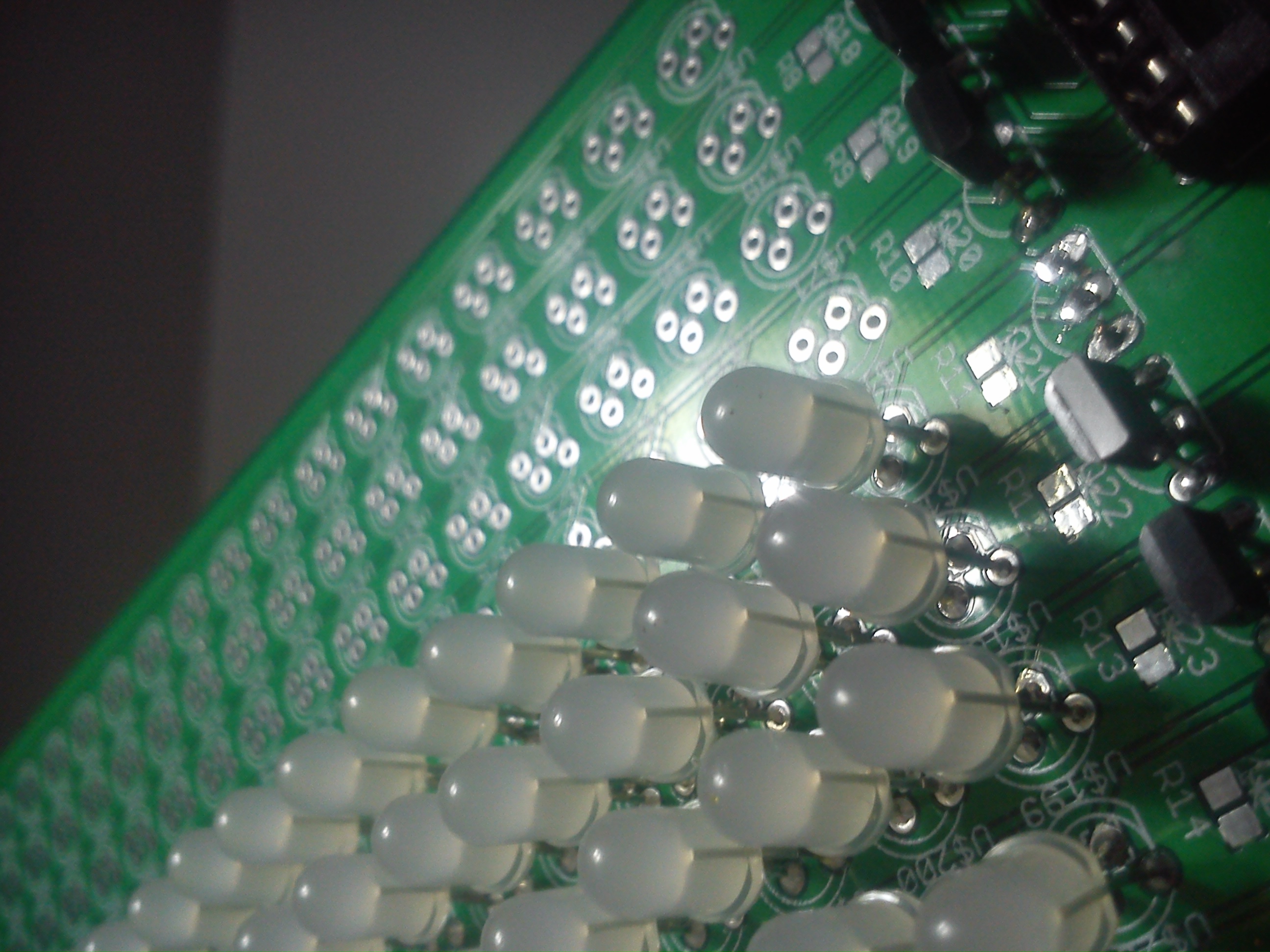
- x256, 5mm RGB LED
- Common anode for PWM driver to sink current, see Figure 1
- x3, PWM driver TLC5940
- 16 channels per chip
- 12-bit PWM resolution
- 6-bit dot correction resolution
- Current sink
- Daisy-chained
- x2, shift register CD4094B
- 8 outputs per chip
- Daisy-chained
- x16, p-channel MOSFET ZVP4424A
- x5, 0.1uF ceramic capacitor, package 0805
- x5, 1uF ceramic capacitor, package 0805
- x2, 10uF tantalum capacitor
- x1, 5V LDO regulator LT1096CT
- x2, 1x6 female connector header
- x1, 2.1mm power connector jack
- x3, 28 position IC socket
- Soldering assembly (solder, iron, braid, etc.)
- Breadboard and jumper wires
- LEDs were arranged in an array of 16x16 (256 LEDs, 48 pins per row) addressed by 3 PWM drivers (48 channels) and 2 shift registers (16 outputs)
- Column data input to PWM drivers through SPI protocol, lighting an entire row at once and row is switched with shift register and new RGB data is sent through PWM driver
- Shift register can’t source enough current to light 16 LEDs so a p-channel MOSFET is used as a high side switch at each row to source required current
- Base code from Kevin Darrah included:
- 8-bit to 12-bit conversion for GS data transmission
- SPI protocol and timer interrupt setup
- Code was expanded on to include:
- Brightness and colour correction
- 8-bit data resolution for easier storage and processing
- Shift register, data buffer and multiplexing
- Schematic capture and PCB layout designed with CadSoft EAGLE
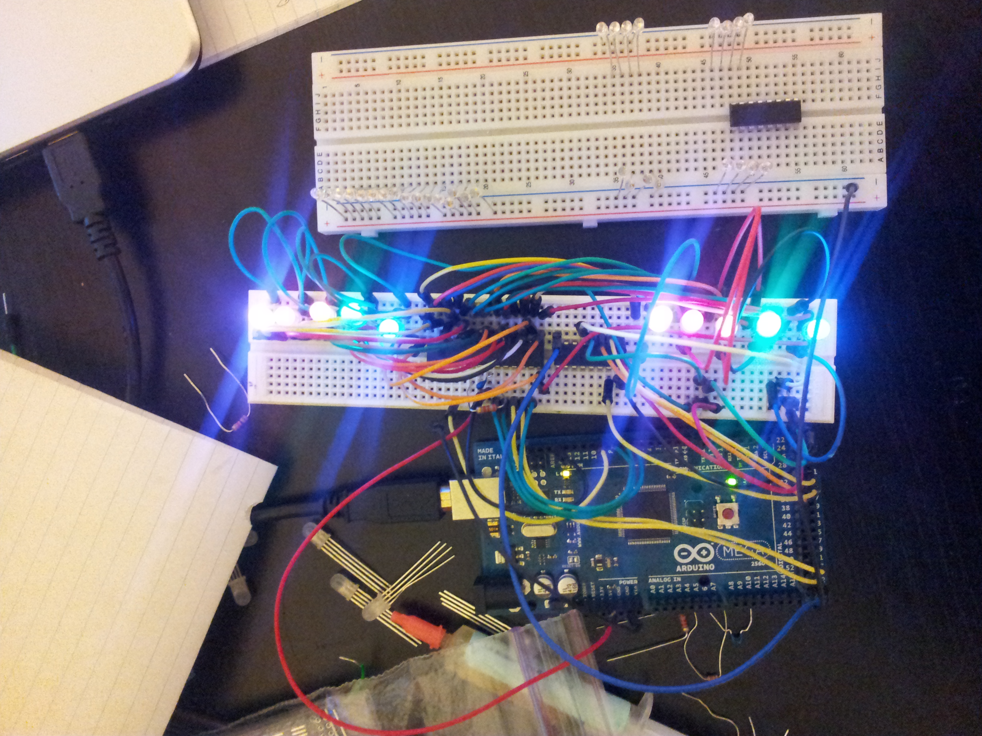
Prototype and assembly of RGB display can be seen from the images and videos below:
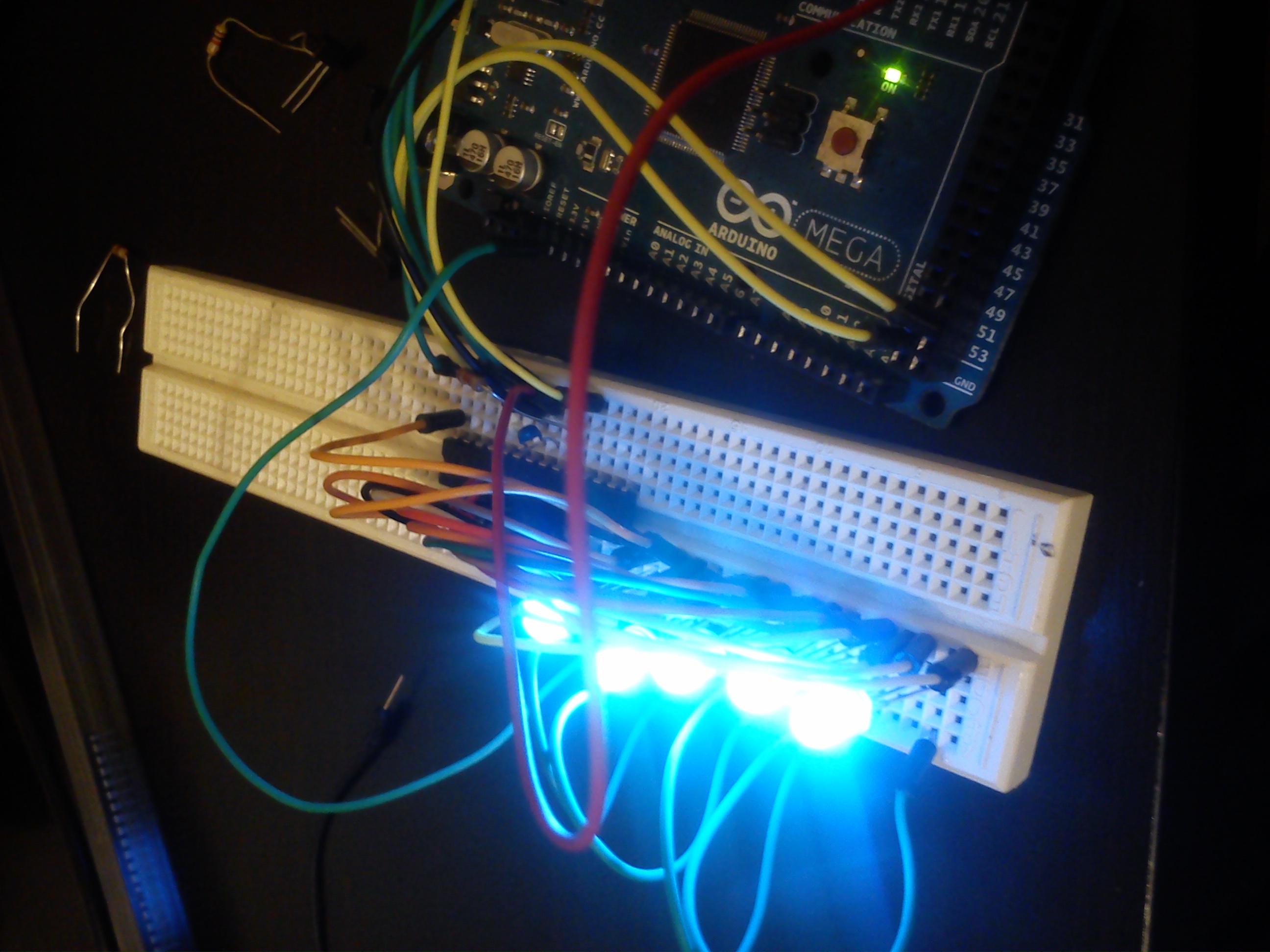
Figure 2: Testing TLC5940
https://youtu.be/0XYK6YoSBJY
Video 1: TLCCycle2, Video of cycling through all the colours with TLC5940
https://youtu.be/0XYK6YoSBJY
Video 2: TLCShift, Video of shifting colours with TLC5940
- Update software to use TLC5940 and TLC5940Mux libraries
- Import images with Python through serial port and show on RGB display