This document provides an overview of the Crypto Voice Module project as well as a brief theory of operations and instructions for how to build one using the provided software builds
The Crypto Voice Module is a system for implementing Secure Voice. The system digitizes voice input using a low-bitrate voice encoder (Codec 2) in this case, encrypts the digital voice signal, and transmits it in a way that allows it to be transferred over a standard analog voice radio signal such as a narrowband FM voice radio, single-sideband radio, or analog telephone.
Conceptually the device is similar to military voice encryption terminals like the KY-99 or commercial versions like the Securenet modules from Motorola. On one end of the device the user plugs in a headset, and on the other end the user connects the device to a radio or analog phone. The user then uses the radio or phone as they usually would, except the sound is being digitized and encrypted by the Crypto Voice Module.
The analog voice is first digitized then sent to a voice encoder or vocoder. A vocoder is an audio compression system optimized for compressing voice so it is understandable even at extremely low bitrates. A typical song is encoded at somewhere between 128-328 kbits/second, while a typical vocoder is able to produce voice down to 1.2-1.6 kbits/second, with some systems able to work at even lower bit rates.
The Crypto Voice Module uses the open source Codec 2 vocoder running in the 1.6 kbits/second mode. This vocder operates on audio blocks 40 ms in duration and is able to represent that 40 ms block in 52 bits.
Once a 52 bit block of compressed audio is produced, it is encrypted using an AES-256 cipher in a cipher feedback mode. This allows a receiver to self-synchronize with a transmitter if a block is lost. A diagram of encryption is shown below.
After a transmission completes or every 5 minutes, a new randomly generated 128-bit initialization vector is obtained from the random number generator. This initialization vector is fed into a KMAC-256 keyed hash algorithm along with a 1048 bit shared key embedded into the Crypto Voice Module. This generates a new 256-bit AES key for each block. This key along with the initialization vector is fed into the AES cipher and produces a stream key which is then XOR-ed with the 52-bit compressed voice block to obtain a 52-bit ciphertext block. 48 of these 52 bits are then copied into a 128-bit shift register which is used as the initialization vector for encrypting the next block.
Decryption operates the same way, but in reverse. Whenever a new initialization vector is produced there is some loss of data as the receiver resynchronizes, but resynchronization can complete within 4 blocks, or 160 ms.
Once the encrypted block is produced, it is transmitted using an audio frequency shift keying modulator. This is a standard means of transmitting digital data at low bit rates over analog mediums intended to transfer voice. This is how the original acoustic coupler modems used to transfer data over phone lines worked. The low data rate required of the vocoder and slow data rate of the frequency shift keying modulator allows the encrypted digital voice signal to be transmitted over a standard narrowband FM radio channel.
At a minimum, you will need the following:
- 1 Raspberry Pi 3 Model B+
or Raspberry Pi Zero(I no longer recommend the Raspberry Pi Zero due to issues getting the USB audio devices to work reliably through the necessary USB hub) 1 USB OTG Hub (if using a Raspberry Pi Zero)- 1 Raspberry Pi Power Supply
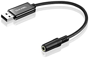
- 2 USB audio receivers (I used these, but anything that says it supports the USB Audio Device Class should work)
- 1 SD card, minimum 64 MB (not GB)
Select a product that is convenient for your use case. For example, I selected a product that has a short TRRS audio cable built into it like this:
I selected a product with TRRS (instead of separate speaker/microphone connectors) because both my headset and radio cable used TRRS connectors. If you don't, find a one that has separate speaker/microphone connectors.
I selected a product with the built-in audio cable because I originally planed to put my completed built in an enclosure, and the built-in cables mean I don't need to buy extension cables to route the audio jacks out the enclosure.
One thing to be cautious of is some of the devices are rather large, and the USB connectors on the PI are spaced rather close together. Whatever you buy, make sure you can actually plug two of them in at the same time.
More advanced builds may involve additional components to make the design more polished or portable, such as
- USB phone charger instead of a power supply (get one that has at least one port that outputs as close to 2.5A output as possible)
- Micro USB power switch cable to allow power to be disconnected without unplugging USB connectors
- SD card extenders to make it easier to insert/remove the SD card
- Enclosure to contain the build
- Portable LCD and keyboard/numpad to use the Console Interface
- Buttons to utilize the keypad, for screenless operation
Note that the system works very well using phone charger battery instead of a power supply. When idle, the software consumes about 1.5 W on a Raspberry Pi 3B+. The software does not require a lot of power, and this design is well-suited to portable applications.
If you decide to put it in an enclosure, it is recommended that you do not do so until you go through the programming and configuration process.
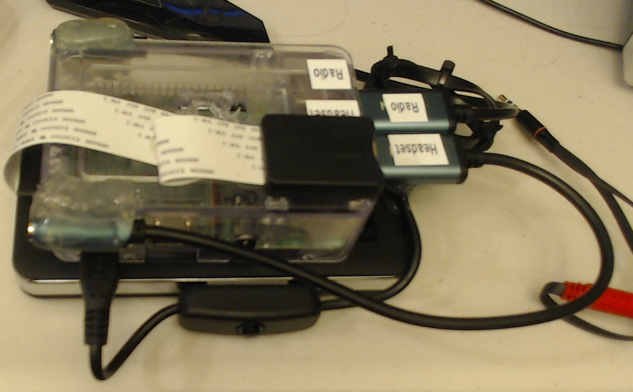
This section shows an example build that the author made. With some slight modification this build could be put into an enclosure for improved portability.
- 1 Raspberry Pi Model 3B+ with enclosure and heatsinks.. You do not need the power supply. If you put the build in an enclosure you do not need an enclosure for the Pi.
- 1 Cell phone battery charger (I used a spare one I had). See above sections for power supply requirements. If you wish to attach the power button to the side of the battery you will need a reasonably thick battery
- 2 MISO USB Audio devices
- 1 Micro USB Power Switch cable
- 1 Micro SD Extension Cable. This makes it easier to access the SD card when the Pi is mounted to the battery pack
- 1 SD Card. Likely any SD Card you have will work
- 1 Short Micro USB Cable
-
Follow the instructions that came with the Pi to install the heatsinks and install the Pi into its case
-
Insert the SD Extension Cable into the Pi's SD card slot
-
Use hot glue or heavy duty double-sided tape to attach the SD Extension Cable to the top of the Pi enclosure. If the ribbon cable is too long, fold the ribbon cable in place using a dab of hot glue
-
Install the USB Audio devices into the bottom USB ports of the Pi
-
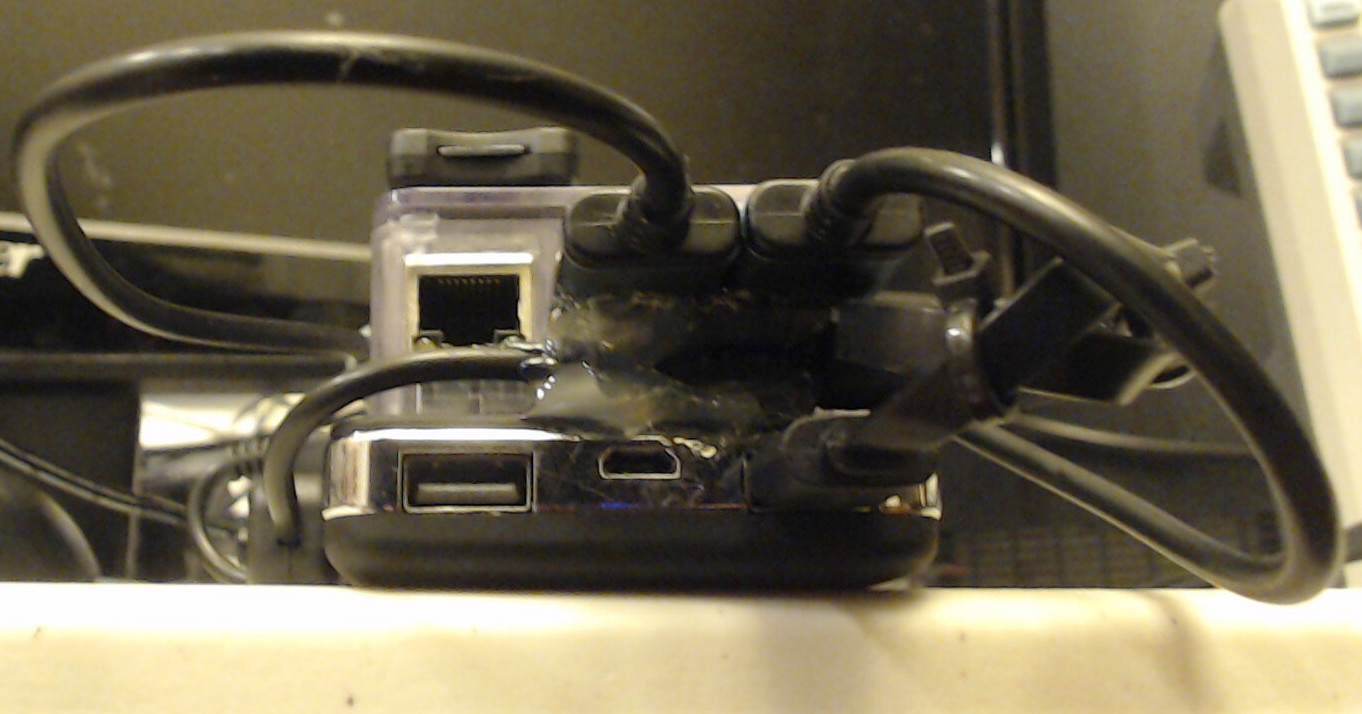
Use hot glue or heavy duty double-sided tape to attach the Pi to the top of the battery pack. If there are charge indicator lights or power buttons, try not to obstruct them
-
Plug the Micro USB Cable into the Micro USB Power Switch. Plug the Male side of the Micro USB Power Switch into the Pi's Power port.
-
Route the Micro USB Power Switch cable under the USB Audio devices so that they are wedged between the battery pack and the USB Audio device dongles. Hot glue the cable to the battery pack and USB Audio devices to to prevent them from being bent or damaged, taking care that the USB cable is not pushing them above horizontal.
-
Use heavy duty double-sided tape or hot glue to attach the power switch to the side of the battery
-
Hot glue the audio connectors from the USB Audio devices to the sides of the Pi enclosure. As cables will be plugged and unplugged into these connectors, ensure you use plenty of glue to hold the connectors firmly in place
-
Plug the USB A side of the cable into the highest power outlet of the battery pack
-
Label the USB Audio Devices once you have gone through the configuration process and know which one is the headset device and which is the radio device
- Download the release_raspberrpi.zip release for your model of Raspberry Pi. This is a heavily customized version of the Linux software that normally runs on a Raspberry Pi and will not run anything else but the barebones software necessary to run the crypto_transceiver software. Note: you only need to flash the SD card once. For subsequent firmware updates you only need to use the zImage file
- Unzip the release_raspberrypi.zip. You should then have a file named sdcard.img
- I recommend using balenaEtcher to flash the image onto the SD Card. Install the software and follow the prompts, selecting the sdcard.img file when asked to supply an image to write to the SD Card.
There still will need to be some configuration which needs to be performed on the device the first time it is powered on. To do this, ensure a programmed SD card with key is installed in the Raspberry Pi, both audio devices are plugged into their own USB ports, a monitor is connected to the Raspberry Pi through the HDMI connector, and a keyboard is connected to a USB port.
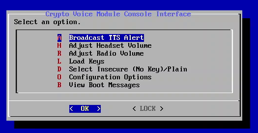
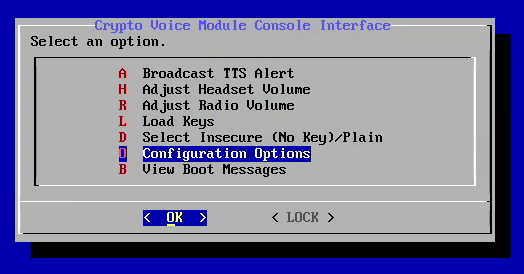
Power on the device. After a few seconds, the boot process should complete; and you should see a configuration interface displayed on your screen.
You will first need to assign each USB audio device as either the Headset device or the Radio device. To do this:
-
Highlight "Configuration Options" and press Enter
-
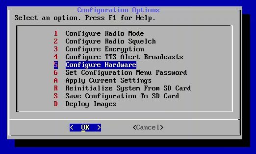
Highlight "Configure Hardware" and press Enter
-
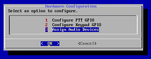
Highlight "Assign Audio Devices" and press Enter
-
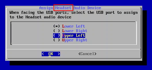
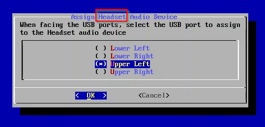
While facing the USB ports of the Pi, use the arrow keys to select which port the audio device you wish to use for the Headset is connected to.
-
Confirm your choice by pressing Spacebar. The selection should now have a star next to it. Then press Enter
-
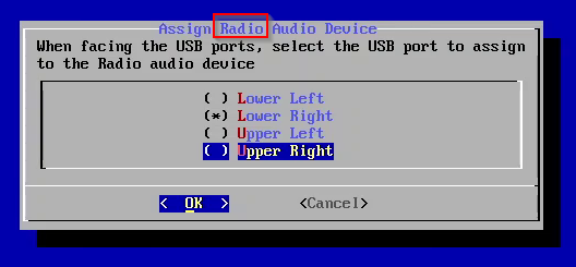
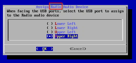
Use the arow keys to select which port the audio device you wish to use for the Radio is connected to.
-
Confirm your choice by pressing Spacebar. The selection should now have a star next to it. Then press Enter.
Next you will need to adjust the audio settings for the Headset and Radio devices. To do this:
-
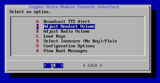
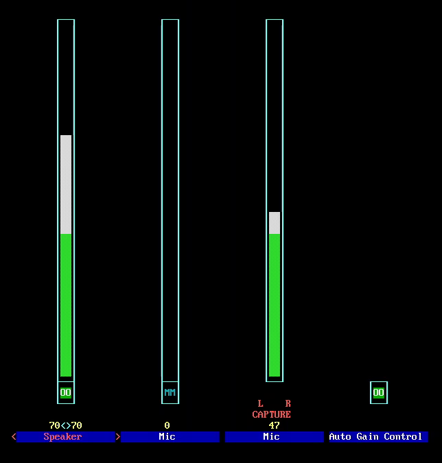
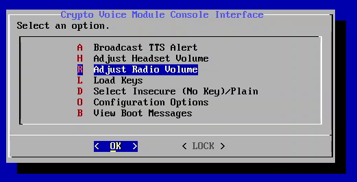
Highlight "Adjust Headset Volume" and press Enter. A configuration screen will appear.
-
The following are the configuration settings I use. Navigate between settings by pressing the Left and Right arrow keys. The "Mic" setting that is set to 0 appears to be some sort of sidetone, so I always turn it off. Auto Gain Control can be toggled by highlighting it with the arrow keys and pressing "m". Additional help is available by pressing F1
-
When the settings are set as desired, press Escape to exit
-
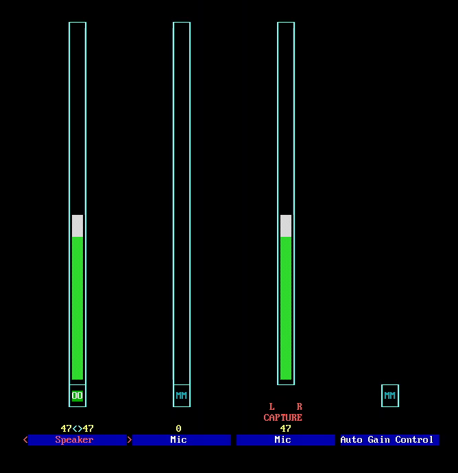
Highlight "Adjust Radio Volume" and press Enter. A configuration screen will appear.
-
The following are the configuration settings I use. Navigate between settings by pressing the Left and Right arrow keys. As above, I turn off the sidetone. It is also important on the Radio device that Auto Gain Control be turned Off. If the settings are too high the signal can become clipped/distorted.
-
When the settings are set as desired, press Escape to exit
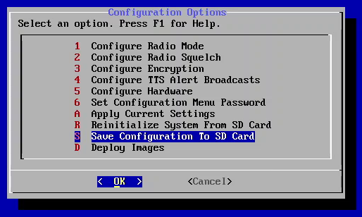
If you have not already done so, create an encryption key by following the "Generating and Saving a Key" step above. You can also adjust other settings as desired. When you have finished, select "Save Current Settings to SD Card".
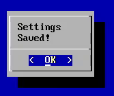
If this is successful, you should see a messsage to that effect.
-
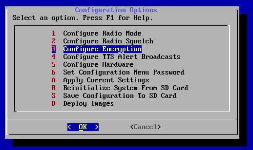
Highlight "Configuration Options" and press Enter
-
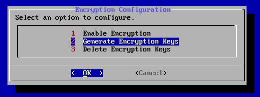
Highlight "Configure Encryption" and press Enter
-
Highlight "Generate Encryption Keys" and press Enter
-
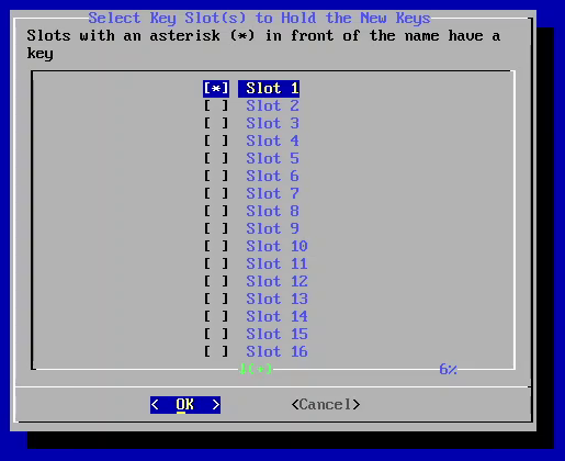
Generate as many keys as desired by selecting the desired Key Slot and pressing Spacebar.
-
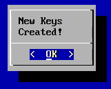
When finished, press Enter. A notification indicating keys have been generated will be shown
Some functions can be performed using buttons connected to the Pi GPIO header:
- Headset volume
- Plain/Secure toggle
- Key Load
- Key Select
- Push to Talk
- TTS Alert Broadcasts
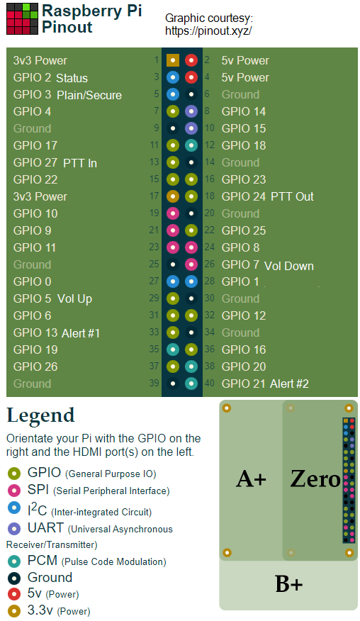
The default pin assignments are listed in the diagram above. All input pins default to Active Low with the internal pull-up resistor enabled. All output pins default to Active Low, open drain.
Push to Talk is the only I/O that needs to be enabled.
-
Highlight "Configuration Options" and press Enter
-
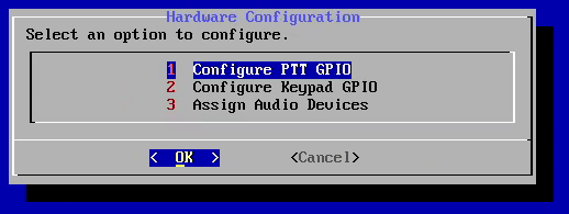
Highlight "Configure Hardware" and press Enter
-
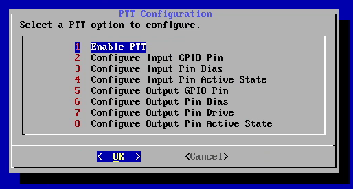
Highlight "Configure PTT GPIO" and press Enter
-
Highlight "Enable PTT" and press Enter
-
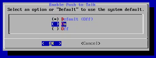
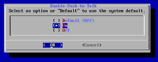
Use the arow keys to select "On"
-
Confirm your choice by pressing Spacebar. The selection should now have a star next to it. Then press Enter
The software has the ability to broadcast two pre-configured messages as Text To Speech Alerts using the Console Interface or the keypad. To Configure these:
-
Highlight "Configuration Options" and press Enter
-
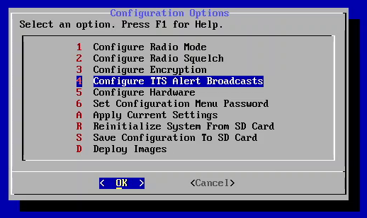
Highlight "Configure TTS Alert Broadcasts" and press Enter
-
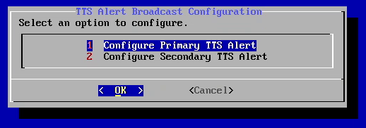
Hightlight "Configure Primary TTS Alert" and press Enter
-
Using the Keyboard, enter a message and press Enter. Messages cannot exceed 160 characters in length
-
Hightlight "Configure Secondary TTS Alert" and press Enter
-
Using the Keyboard, enter a message and press Enter. Messages cannot exceed 160 characters in length
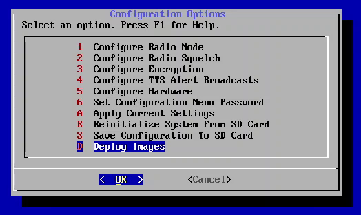
The Console Interface has capabilities for creating duplicate SD Cards with the same hardware, firmware, and radio configuration, in scenarios where multiple devices will be deployed to the field. These devices are "locked", meaning the user is prevented from making changes to the configuration or (optionally) accessing the Console Interface at all.
-
Highlight "Configuration Options" and press Enter
-
Highlight "Deploy Images" and press Enter
-
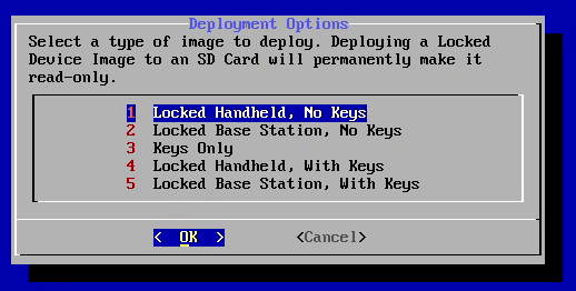
You will see a number of options for images to deploy onto an SD Card or USB Drive. "Locked" Device images are written so that the user cannot change system configuration, and the SD Card is then permanently made read-only to prevent tampering. "Handheld" images additionally lock the display entirely so it cannot be used. This option is recommended when deploying devices which will not have a screen connected.
Locked Device images with keys are only recommended in situations where a single SD Card is used to initialize multiple devices which are deployed without an SD Card installed. Ideally the SD Card is destroyed after the devices are initialized. In this configuration the device is rendered inoperable by disconnecting power.
Locked Device images without keys are recommended in situations where each device is deployed with in SD Card installed. Keys are then loaded from a "Keys Only" SD Card or USB Drive, and that Card/Drive is removed from the device prior to deployment. In this configuration key zeroize is accomplished by disconnecting power, and when power is reconnected the device can still function in an insecure mode.
"Keys Only" images will write just the encryption keys to either an SD Card or USB Drive. As mentioned above, they are designed to work in combination with Locked Device images without keys. These cards/drives are not write-protected after the process completes, and it is recommended that after keys are loaded onto devices the media used for key storage be destroyed or (if the storage media supports it) securely erased.
-
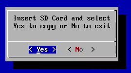
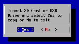
Once an option is selected, you will be prompted to insert storage media. Locked Device images can only be written to SD Cards.
Keys can be written to either an SD Card or a USB Drive. If both a USB Drive and SD Card is installed in the system, the USB Drive will be used. Select "Yes" once you have done so to start the process.
-
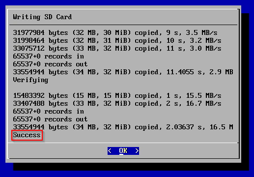
Once you have selected "Yes", the image writing process will start. At the end you should see a message that says "Success".
-
Once you see "Success", if you do not wish to write protect the SD Card you can remove it. If the SD Card is installed in the system once you press "OK", it will be write-protected. You will see one of three messaages:
- "Write Protect Succeeded": The write protection process completed successfully, and the data on the SD Card can no longer be modified.
- "Could Not Write Protect": The SD Card does not support write protection (or you removed it from the device prior to pressing "OK", and the card is not write protected.
- "Write Protect Doesn't Work": The SD Card claimed to write protect the drive, but the software was still able to write to it. If this happens you will find a file named "BAD_WP" if you read that SD Card using a PC.
-
Once you have selected "OK" you will be prompted to copy the image to another storage media by pressing "Yes" or stop the deployment process by pressing "No".
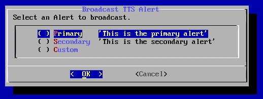
The system has the ability to broadcast two pre-configured Text To Speech Alerts, and custom Alerts can be broadcast using the Console Interface.
Follow the steps below to use the "TTS Alert Broadcast" feature with the Console Interface:
-
Highlight the "Broadcast TTS Alert" option and press Enter
-
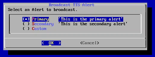
Using the arrow keys, highlight either the Primary, Secondary, or Custom Alert option
-
Select the option by pressing Spacebar
-
Press Enter to broadcast the Alert. You will hear it play over the headset.
-
If you select "Custom" Alert, then an input box will appear prompting you to enter the message to be broadcast
-
Type the message using the keyboard, then press Enter to broadcast it. You will hear it play over the headset
The keypad has two multi-function "action" buttons: the "primary" action button and the "secondary" action button. A triple-press of either action button will activate the primary TTS alert broadcast or the secondary TTS alert broadcast.
Follow the steps below to use the "Key Select" feature with the Console Interface:
-
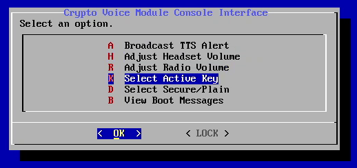
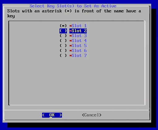
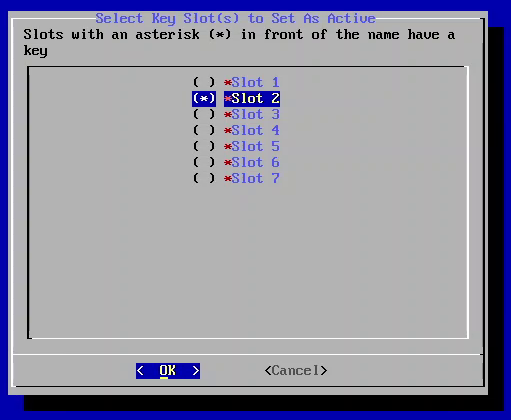
When keys are loaded into the device a "Select Active Key" option appears in the Main Menu. Highlight "Select Active Key" and press Enter
-
Use the arrow keys to highlight the key you wish to select as the Active Key
-
Select the key by pressing Spacebar. An asterisk will appear net to the Key Slot.
-
Confirm your choice by pressing Enter. A confirmation chime will be played over the headset
Follow the steps below to use the "Key Select" feature with the kaypad:
- Press and hold the primary action button. You will hear "Key Select" over the headset
- With the primary action button held down, press and hold the secondary action button. You will hear the index of the key currently in use.
- With the primary action button held down, release the secondary action to go the next key slot index with a key.
- With the primary action button held down, press and hold the secondary action button. You will hear the index of the currently selected key.
- Continue this press and release until you hear the index of the key you wish to use.
- With both the primary and secondary action buttons held down, release the primary action button to update the key currently in use. You will hear a confirmation notification over the headset.
- Release the secondary action button.
While the primary action button is held down and the secondary action button is released, release the primary action button to cancel the key selection process.
The Key Load feature will load keys into the device under the following conditions:
- Keys have not already been loaded into the device
- There is a USB Drive or SD Card containing keys installed in the device
When keys are loaded into the device, the Key Index will be set to the first Slot containing a key
Follow the steps below to use the "Key Load" feature with the Console Interface:
-
Ensure an SD Card or USB Drive containing keys is installed in the device.
-
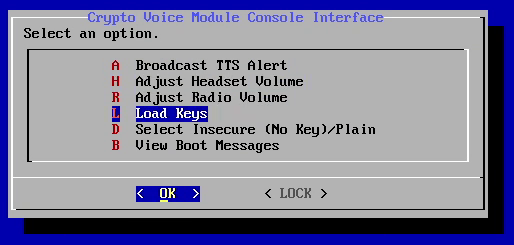
When no keys are loaded into the device a "Load Keys" option appears in the Main Menu. Highlight "Load Keys" and press Enter
-
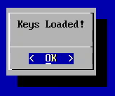
If the keys were loaded from the SD Card or USB Drive, a message box will be displayed indicating keys were loaded, and a confirmation chime will be played over the headset
Follow the steps below to use the "Key Load" feature with the keypad:
- Ensure an SD Card or USB Drive containing keys is installed in the device.
- Press and hold the secondary action button. You will hear "Key Load" over the headset.
- With the secondary action button held down, press and hold the primary action button. If there is a card/drive with keys and the device is ready to load them (see above conditions), you will hear "Ready to Load" over the headset. Otherwise you will hear "Cannot Load".
- With both the primary and secondary action buttons held down, release the secondary action button to Load the keys. You will hear a confirmation notification over the headset confirming keys have been loaded and the Index of the Key Slot currently in use.
- Release the primary action button.
- Remove the SD card or USB drive containing keys from the device.
While the secondary action button is held down and the primary action button is released, release the secondary action button to cancel the key selection process.


