This repository contains a set of projects I've developed while taking the Computer Vision with Embedded Machine Learning course, taught by Shawn Hymel and supported by the Edge Impulse online tool. The goal of these projects is to deploy different types of image classification models on an microcontroller.
As a use case, the models are trained to classify electronics components such as resistors and capacitors : you can find examples of such components in the datasets/ folder.
This isn't 'yet another hand-in' from a course project, and here's why this could be interesting to you:
- Instead of using the recommended hardware platforms for the course as of November 2021 (i.e., OpenMV Camera or Raspberry Pi 4 with PiCamera), I've used an Arduino Nano BLE 33 Sense connected to an OV7670 CMOS camera.
- This work shows how to create a data capture and live inference setup with the Arduino + OV7670 camera, and also how to integrate the TensorFlow Lite models trained in Edge Impulse in Arduino.
- I've followed the proposed 'electronic component' classification task, classifying components into 4 buckets : {'background', 'capacitor', 'LED', 'resistor'}. However, I've decided to make it harder by using 4 to 5 different components per class. E.g., I've built the LED dataset with photos from 4 different LEDs, the capacitor dataset with 5 different capacitors, etc.
- Instead of simply following the tutorial script, I've experimented with different model types and hyperparameter sets, comparing the live performance in the chosen classification task along two metrics: (i) accuracy and (ii) sensitivity to the position of the object in the frame. The results can be checked in this page.
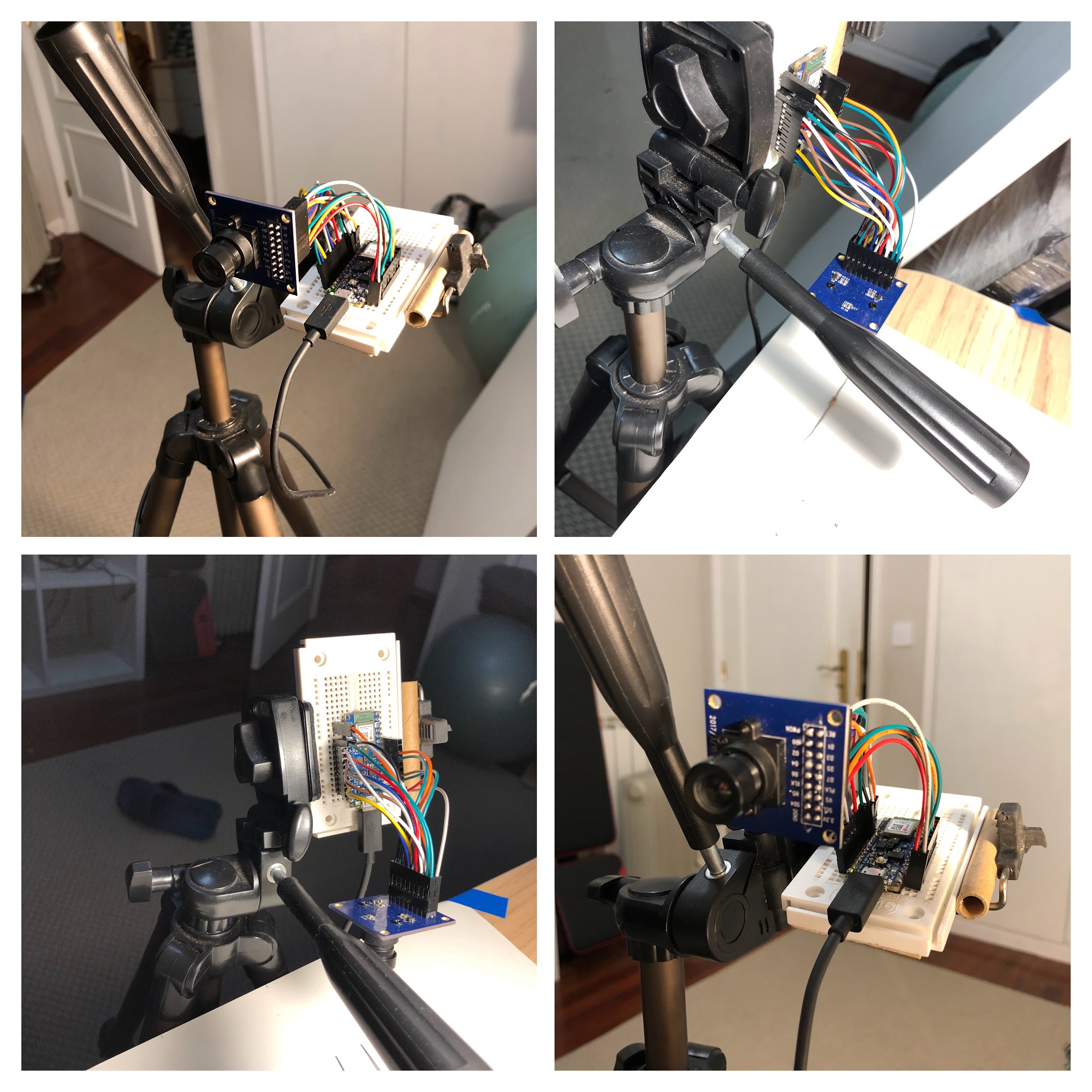
I've used the following setup:
- 1 Arduino Nano 33 BLE Sense
- 1 OV7670 CMOS camera (e.g., like this)
- 1 small breadboard (e.g., this)
- 18 M/F jumper wires, 10 cm long (e.g., this)
- 1 'smartphone' tripod (e.g., this), used to hold the Arduino + Camera setup in place, making it easier to run live inference experiments
The images below show how my setup looks like.
Notice that I've also taped a blank A4 sheet to the top of my desk, which served as a background for both data captures and live inference tests.
It is also important to ensure consistent lighting conditions between your training / testing data and live inference (e.g., using the light of a lamp, pointing directly at the blank sheet of paper). Either that, or you must train your classifier with data captured with different lighting conditions, so that to make your classifier 'insensitive' to lighting.
The connections between my particular OV7670 camera module and Arduino Nano 33 BLE Sense are shown in the table below.
These connections can be found in the examples of the Arduino OV767X library, e.g. in the file libraries/Arduino_OV767X/examples/CameraCapture/CameraCapture.ino in the repository.
| Arduino Nano 33 BLE Sense pin | OV7670 CMOs camera pin | OV7670 CMOs camera pin (alt. name) |
|---|---|---|
| +3V3 | 3.3V | - |
| GND | DGND | GND |
| A5 | SDA | SIOC |
| A4 | SCL | SIOD |
| D8 | VS | VSYNC |
| A1 | HS | HREF |
| A0 | PLK | PCLK |
| D9 | XLK | XCLK |
| D4 | D7 | - |
| D6 | D6 | - |
| D5 | D5 | - |
| D3 | D4 | - |
| D2 | D3 | - |
| RX | D2 | - |
| TX | D1 | - |
| D10 | D0 | - |
| GND | PDWN | - |
| +3V3 | RET | - |
Each project in the projects/ folder is designed to be deployed in an Arduino Nano 33 BLE Sense as a .zip library using the Arduino IDE.
To deploy each project, follow these steps (this assumes a hardware setup as described above):
cdto the project directory- Run
makeon the project directory : this will generate a .zip Arduino library, which can then be added to the Arduino IDE - Open the Arduino IDE, and add the resulting .zip file, using the
Sketch > Include Library > Add .ZIP Libraryfeature - Open the sketch via the
File > Examples > <project-name> > nano_ble33_sense_cameramenu - After loading the sketch, deploy via the
Sketch > Uploadmenu - The results from live inference can be read from the serial port in the Arduino IDE, using the
Tools > Serial Monitormenu.
For the special case of project 3, the results must be visualized with the Processing desktop application, using the sketch available in libraries/Arduino_OV767X/extras/CameraVisualizerRawBytes.pde (more details on Processing the in the 'Data Capture' section below).
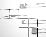
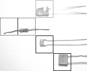
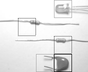
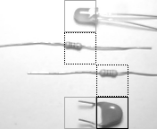
In this case, the detected objects will be surrounded by squares of different shades of gray, as shown in these images:
For reference, the table below shows the correspondence between each line type and classification category for the images above.
| Line type | Category |
|---|---|
| Solid gray | LED |
| Solid black | Capacitor |
| Dashed black | Resistor |
Notes:
- Ensure the Arduino Nano 33 BLE Sense and the correct serial port are selected in the
Toolsmenu. For further details, refer to the Arduino documentation. - In order for this to work, you'll need to update the OV767X library with an extra method :
isGrayscale(). You can use the library version that ships in this Github repository in thelibraries/folder.
I've captured data for my datasets in datasets/ directly with the Arduino + OV7670 setup : this way, I've ensured that the data used to train my image classifiers is captured in the same way as the data used in live inference tests.
I've used the Processing desktop application (v4.0b2) collect the image data captured by the Arduino. Processing allows you to run Java 'sketches' that:
- Connect to the serial port (similarly to the Arduino IDE)
- Read the image data captured and sent by the Arduino over the serial port
- Allow you to display, transform and save the images in a typical format such as
.pngor.jpg
I've included two sketches in the repository, as part of the custom version of the Arduino OV767X library, in the libraries/Arduino_OV767X directory. These can be used in conjunction to get you started with your data collection efforts:
examples/CameraCapture.ino: when uploaded to the Arduino, it continuously performs the following operations :
- Captures an image in QCIF and grayscale format (176 x 144 px, only the 'luminance' byte of the YUV422 format)
- Crops the image at the center to a custom size, using the same routines as in the live inference sketches
- Sends the cropped image over the serial port
extras/CameraVisualizerRawBytes.pde:
- Reads an image from the serial port. Image size and format must be specified in the sketch, using the variables below.
- Displays the image in a pop-up window
- Saves the image in
.pngformat in thedstFolderfolder
| Variable | Descr. |
|---|---|
cameraWidth |
image width (px) as sent by Arduino |
cameraHeight |
image height (px) |
cameraBytesPerPixel |
number of byte per pixel (e.g., 2 byte for RGB565, 1 byte for grayscale) |
dstFolder |
folder where images are saved |
