Sense, Arduino, IDE
In this tutorial, we will describe how to program the ScientISST - Sense development board through the Arduino's Integrated Development Environment (IDE), whether you’re using Windows, Mac OS X or Linux.
Before starting this tutorial, you need to download and install the latest version of the Arduino IDE from: https://www.arduino.cc/en/software [1]. If you don’t have the latest version installed, uninstall Arduino IDE and install it again. Otherwise, it may not work.
After you have the latest Arduino IDE software installed in your computer, open the software to confirm that it is working.
Hovering with the mouse pointer on each button shows a brief description of its function. The following figure summarizes these functionalities:
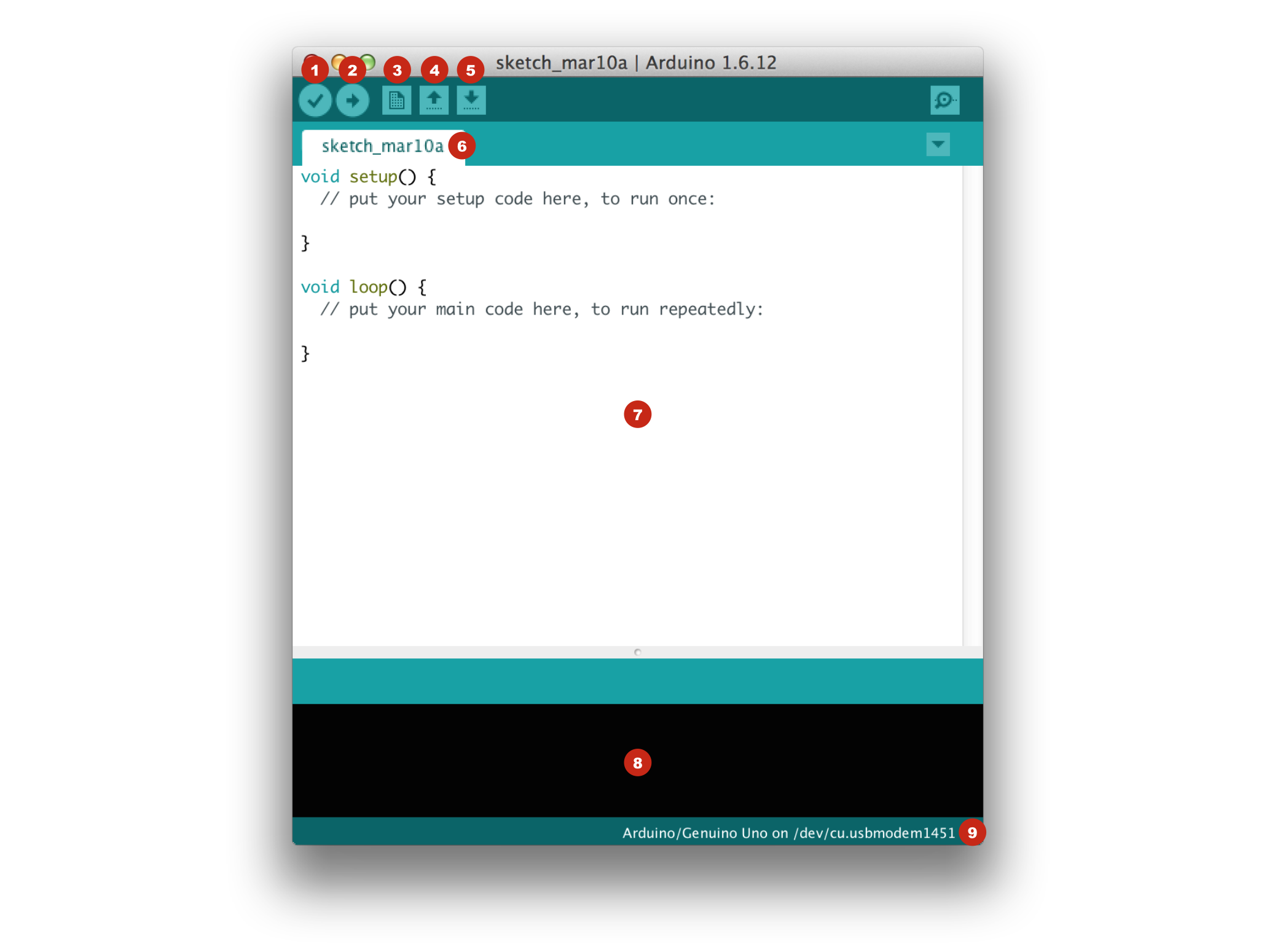 |
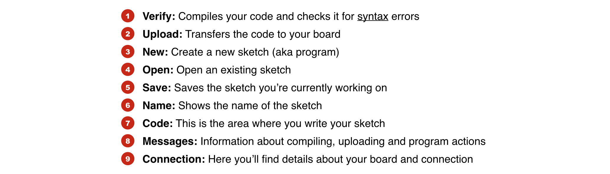 |
Note: To get a better understanding on the Arduino Software (IDE) and its functionalities, a more comprehensive guide on this topic is available at: https://www.arduino.cc/en/Guide/Environment [2].
The ScientISST - Sense development board is built upon the ESP32-WROOM-32, a powerful, generic Wi-Fi+BT+BLE MCU module, which has at its core the ESP32-D0WDQ6 chip. This is why you first need to install the ESP32 add-on in the Arduino IDE in order to program the ScientISST - Sense development board from the Arduino IDE using its programming language (C/C++). To install this add-on, follow these next instructions:
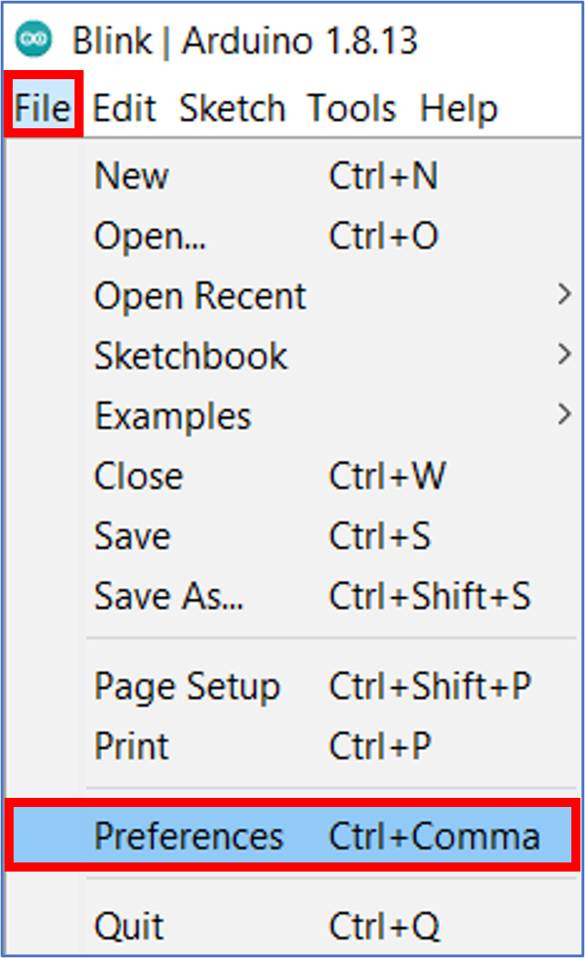
- In the Arduino IDE, go to File > Preferences:
- Enter
https://dl.espressif.com/dl/package_esp32_index.json[3] into the "Additional Board Manager URLs" field (1) in the "Preferences" window as shown in the figure below. Then, click the "OK" button (2):
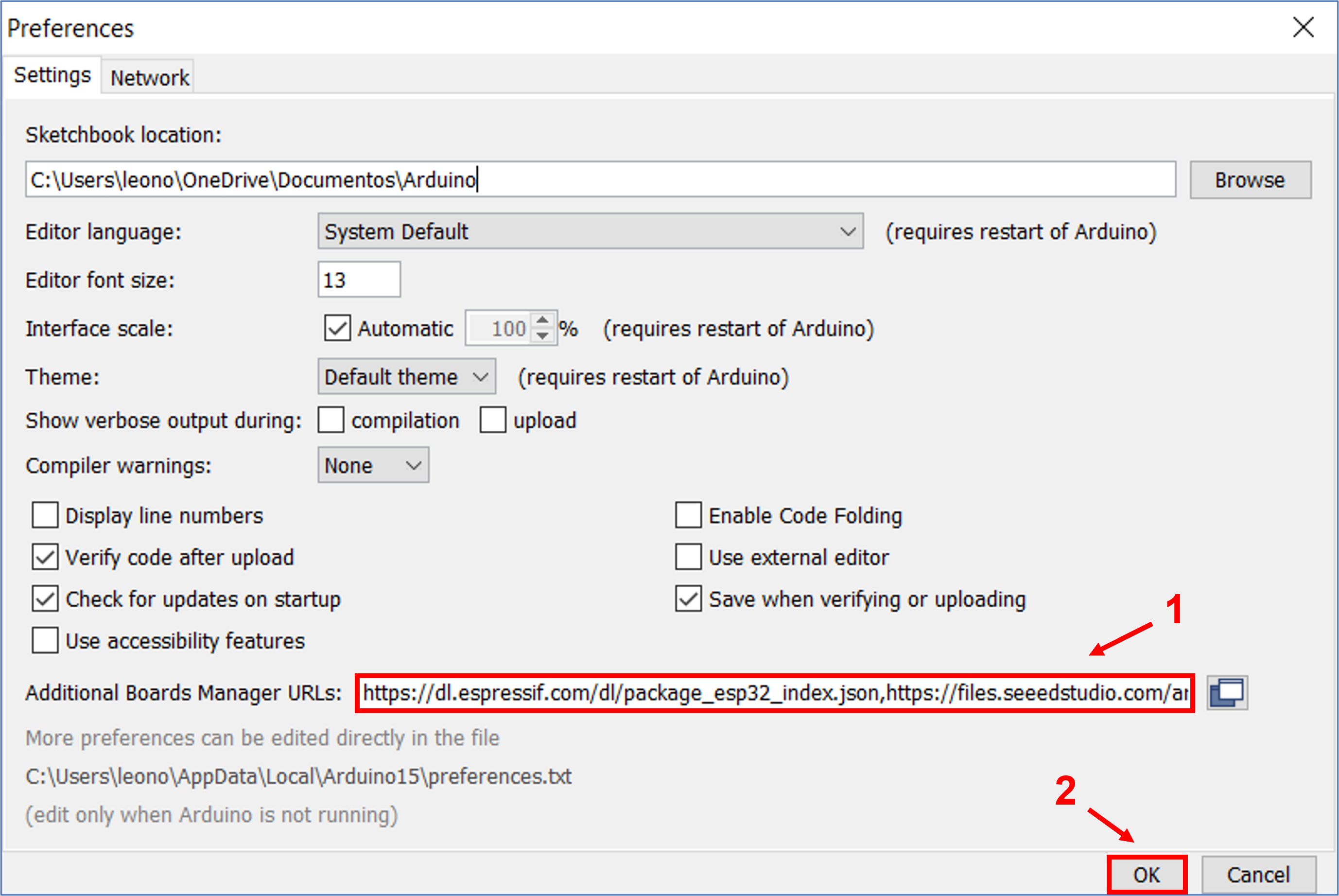
Note: If you already have the URL of another board in the "Additional Board Manager URLs" field, you can separate the URLs with a comma as displayed in the figure above.
- Open the Boards Manager. Go to Tools > Board > Boards Manager
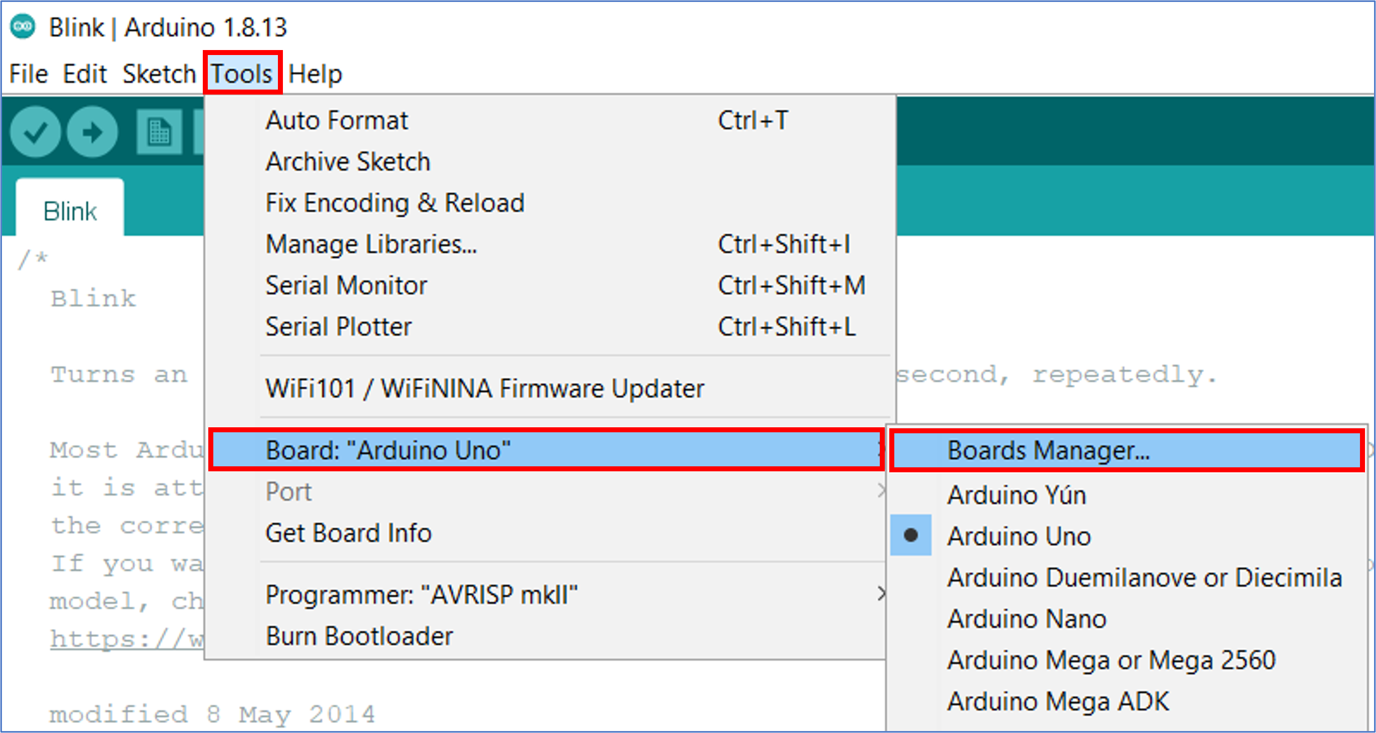
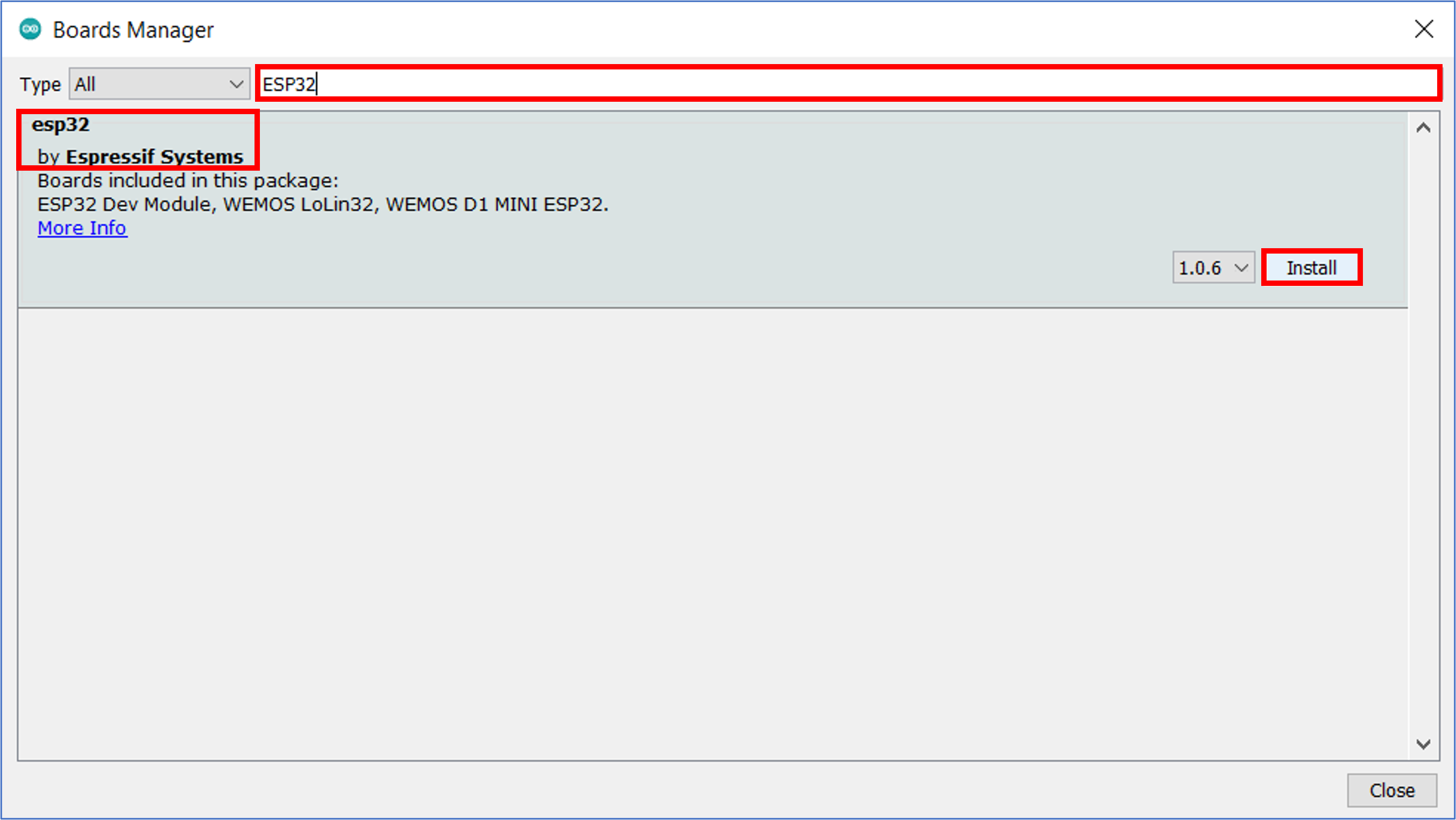
- Search for ESP32 and press the "Install" button for the "esp32 by Espressif Systems":
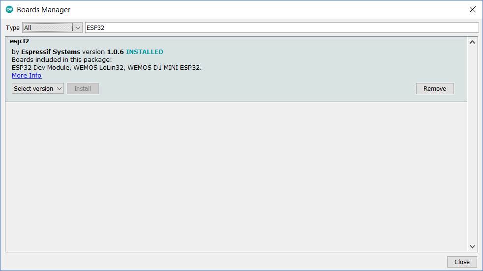
5. The add-on should be installed after a few seconds, as shown in the following figure:
-
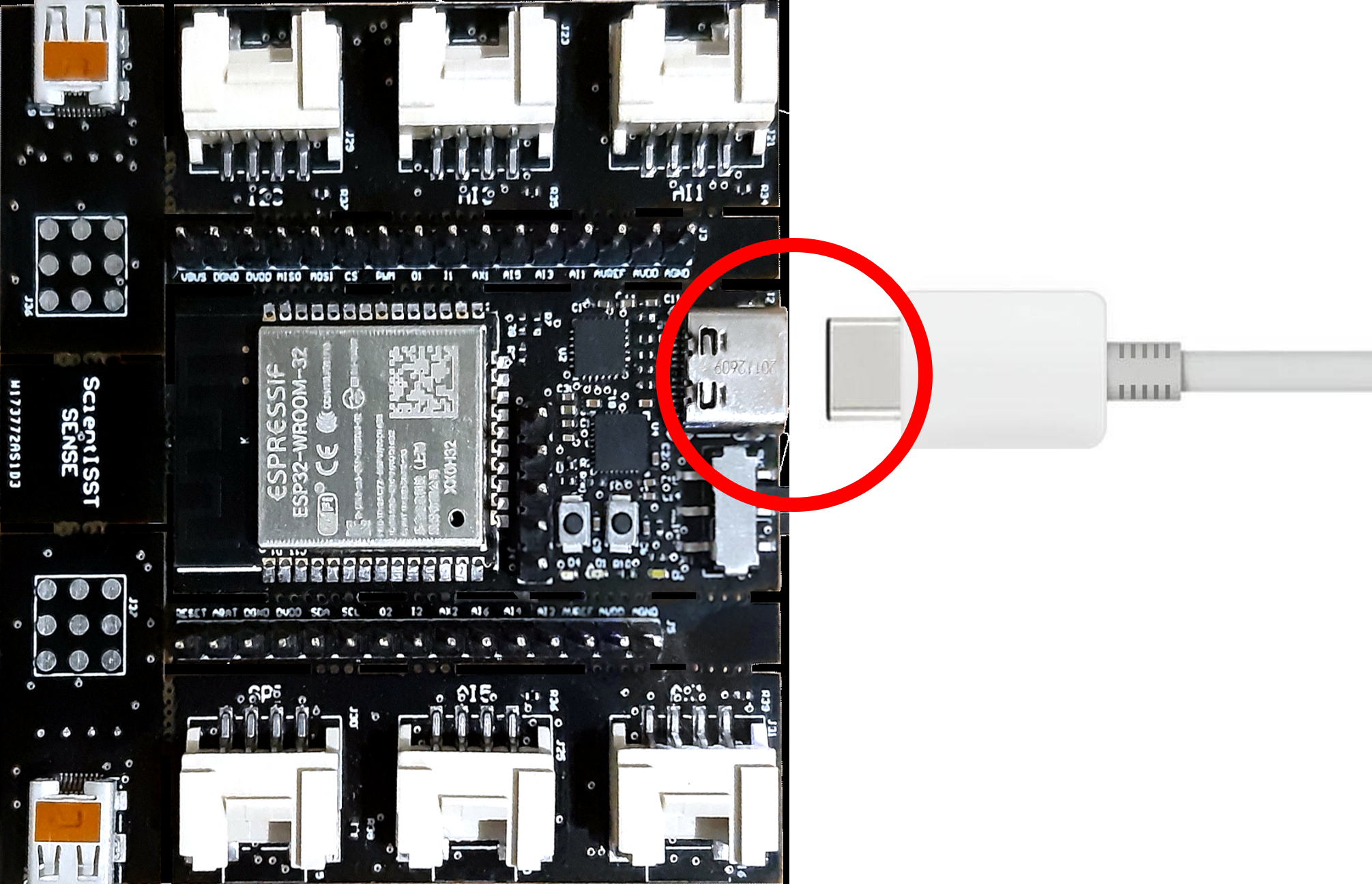
Connect the USB-C cable to your computer and to the corresponding socket on the ScientISST - Sense development board:
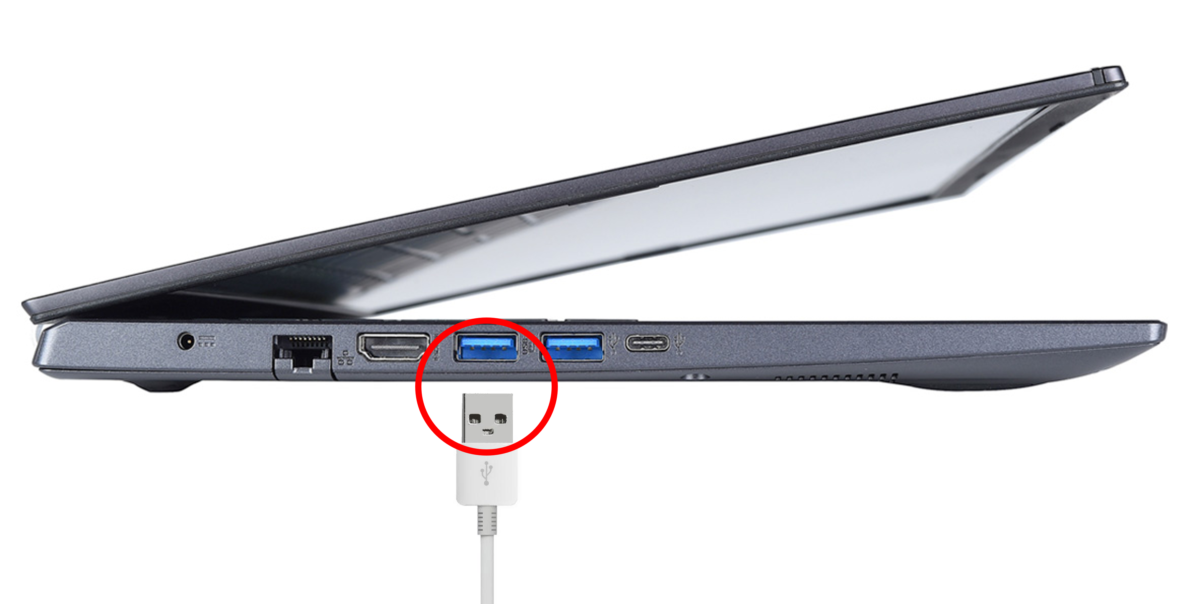
1.1 Connect the standard USB-A connector to your computer:
1.2 Connect the other end to your ScientISST - Sense development board:
At this point, the built-in blue LED on the back of the ScientISST - Sense development board should be on, and the built-in white LED on the front should be flashing repeatedly, if the board still carries the original firmware for the ScientISST - Sense development board.
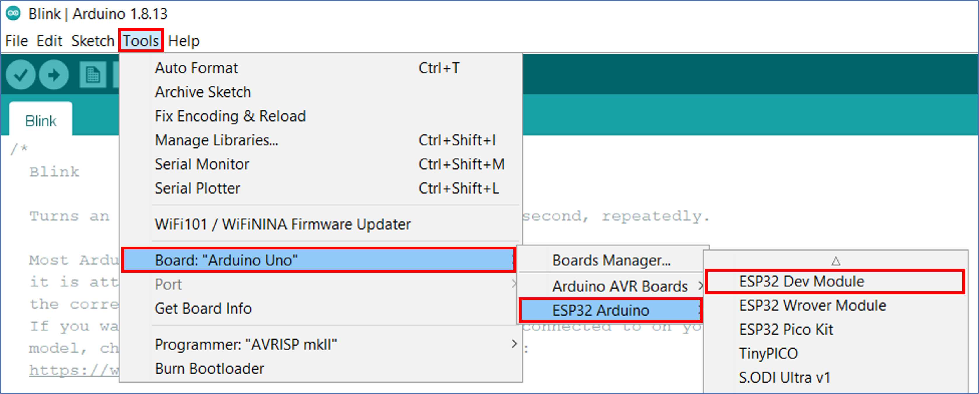
- In the Arduino IDE, go to
Tools > Board > ESP32 Arduinoand select your board model, i.e. ESP32 Dev Module:
- Go to
Tools > Portand select the port that your ScientISST - Sense development board is using. On Windows it should have the prefix COM, followed by an integer number (as is the case in the figure below), and on Mac OS it should have the prefix /dev/cu.usb or /dev/tty.usb. Usually the port of your newly added device appears at the end of the list:
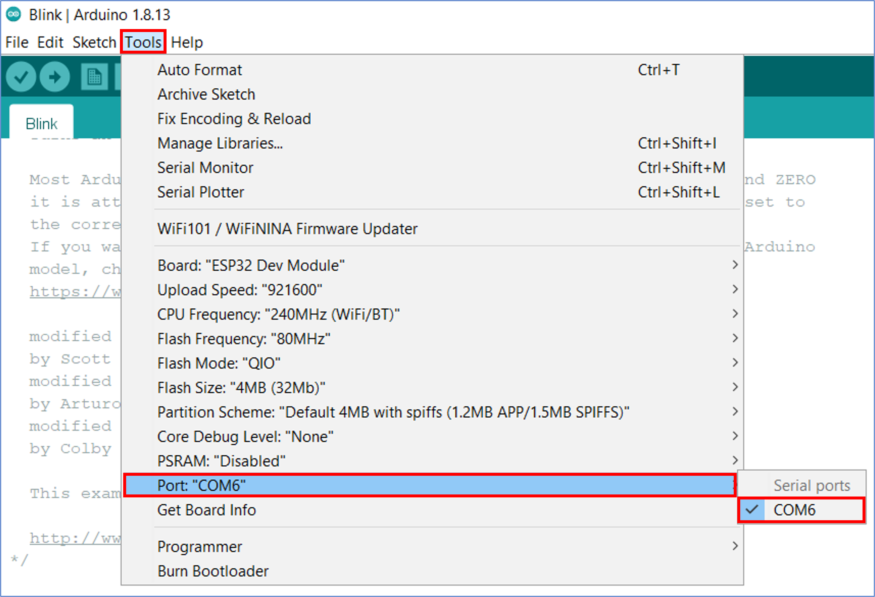
Note: If you don’t see the COM Port in your Arduino IDE, you need to install the CP210x USB to UART Bridge VCP Drivers from: https://www.silabs.com/developers/usb-to-uart-bridge-vcp-drivers [4].
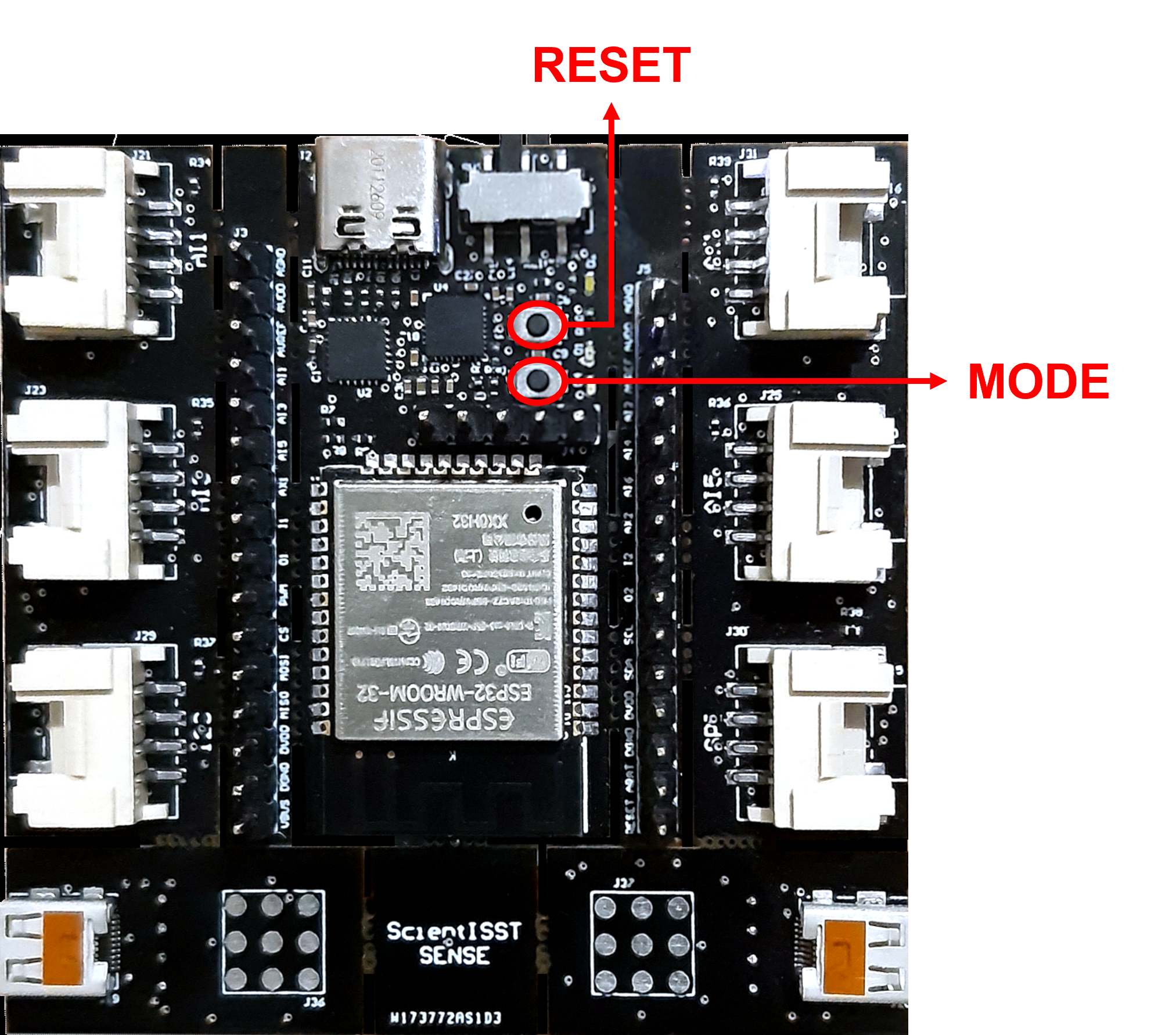
- To upload a sketch with your code written on the Arduino IDE, you must first put your ScientISST - Sense development board on BOOT mode. To do so, you will need to use the RESET and MODE buttons on the ScientISST - Sense development board, shown in the following figure:
Before uploading the sketch:
- Hold down the MODE button.
- Press the RESET button.
- Release the MODE button.
If the previous steps were done correctly, the white LED should have stopped blinking.
At this point, the ScientISST - Sense development board is now on BOOT mode and is ready to have the sketch uploaded to it.
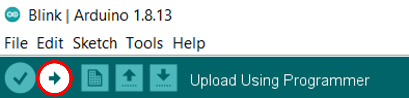
- Upload the sketch to your board by clicking the "Upload" button in the Arduino IDE:
Wait a few seconds while the code compiles and uploads to your board. If everything went as expected, the MESSAGES section of the Arduino IDE should show a notification indicating that the code has been uploaded, and list general information regarding the device and memory use:
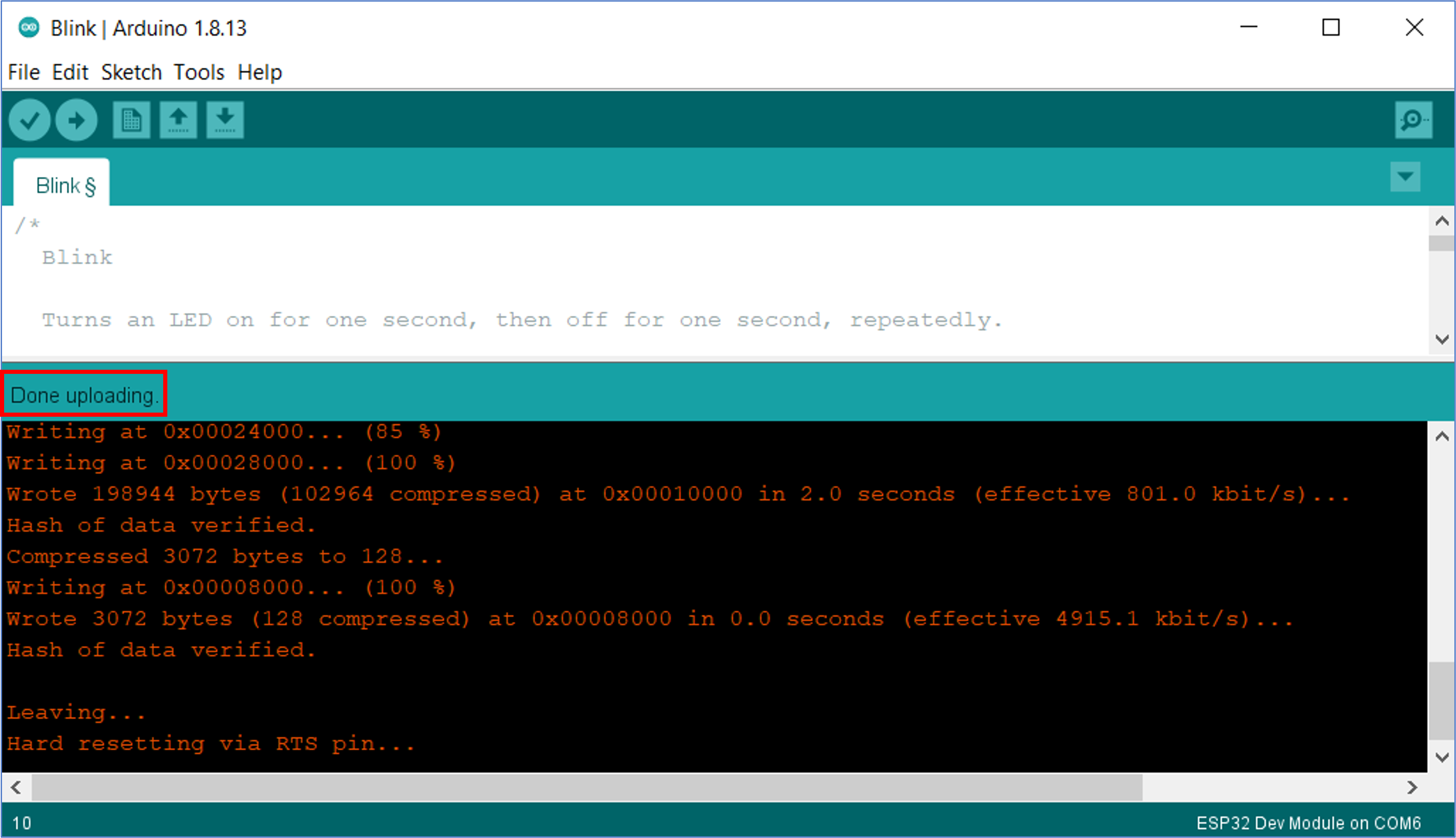
Note: In case you obtain an error during the upload, read the output in the MESSAGES section carefully and you will likely be able to have a rough idea of what went wrong. The most common causes of problems are syntax errors in your code, a mismatching board version on the Arduino IDE, or a wrongly selected port, so please review your code and try to identify any typos or mismatching characters.
- Finally, press the RESET button to put your ScientISST - Sense development board on Execution mode and have it run the uploaded code.
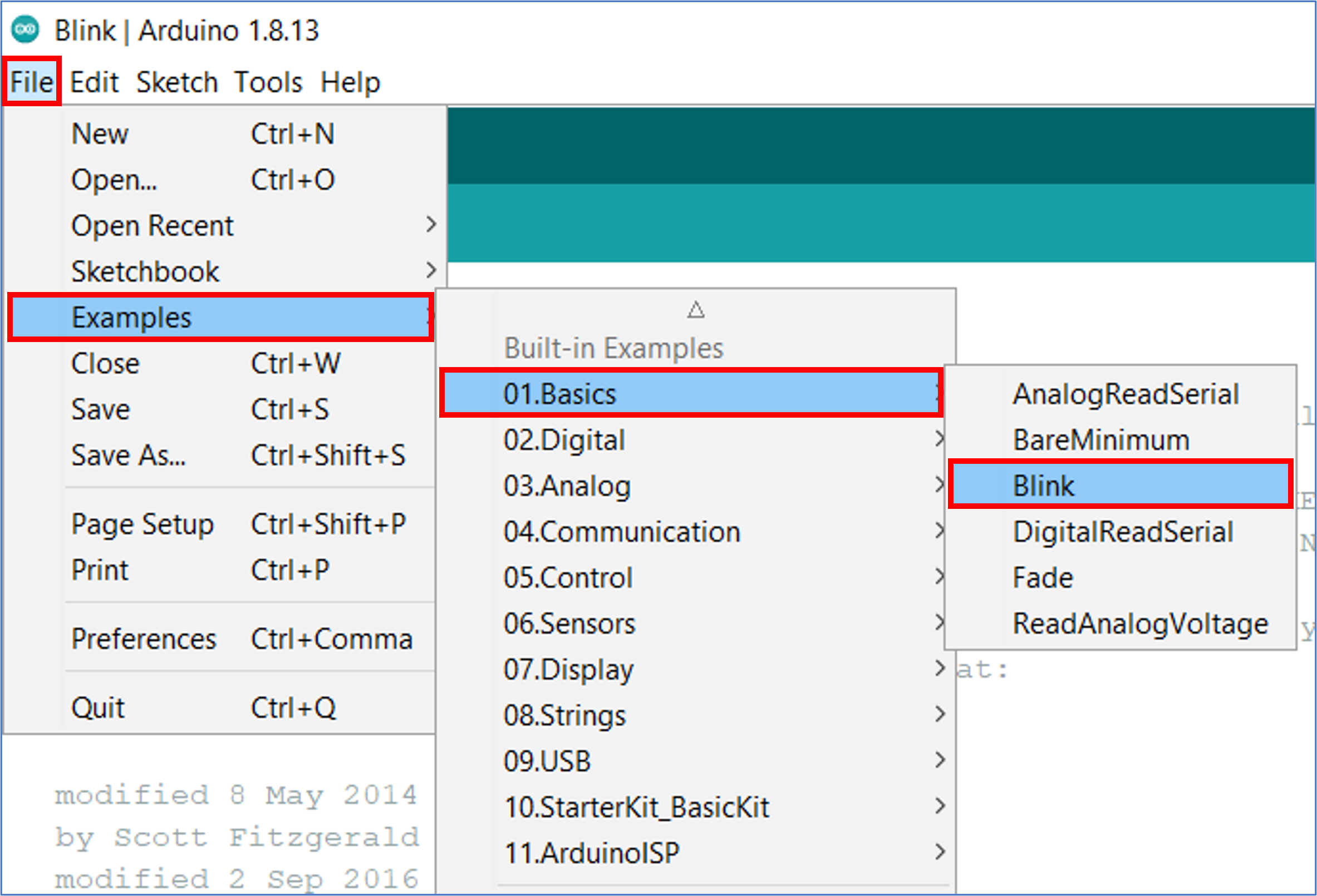
To test your setup, follow the steps from Section III and upload the Blink sketch, one of the built-in examples of the Arduino IDE that can be loaded from File > Examples > 01.Basics > Blink:
Note: Don't forget to replace the
LED_BUILTINin the Blink sketch with the number of the pin connected to the white LED (GPIO 22).
Upon successful completion of the process, the white LED on the front of the board should be on for one second, then off for one second, repeatedly.
1. https://www.arduino.cc/en/software
2. https://www.arduino.cc/en/Guide/Environment
3. https://dl.espressif.com/dl/package_esp32_index.json
4. https://www.silabs.com/developers/usb-to-uart-bridge-vcp-drivers


Contributors: Prof. Hugo Silva; Leonor Pereira; Francisco Melo; Afonso Raposo