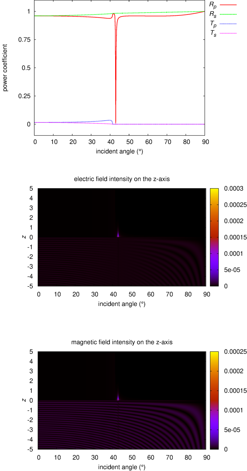
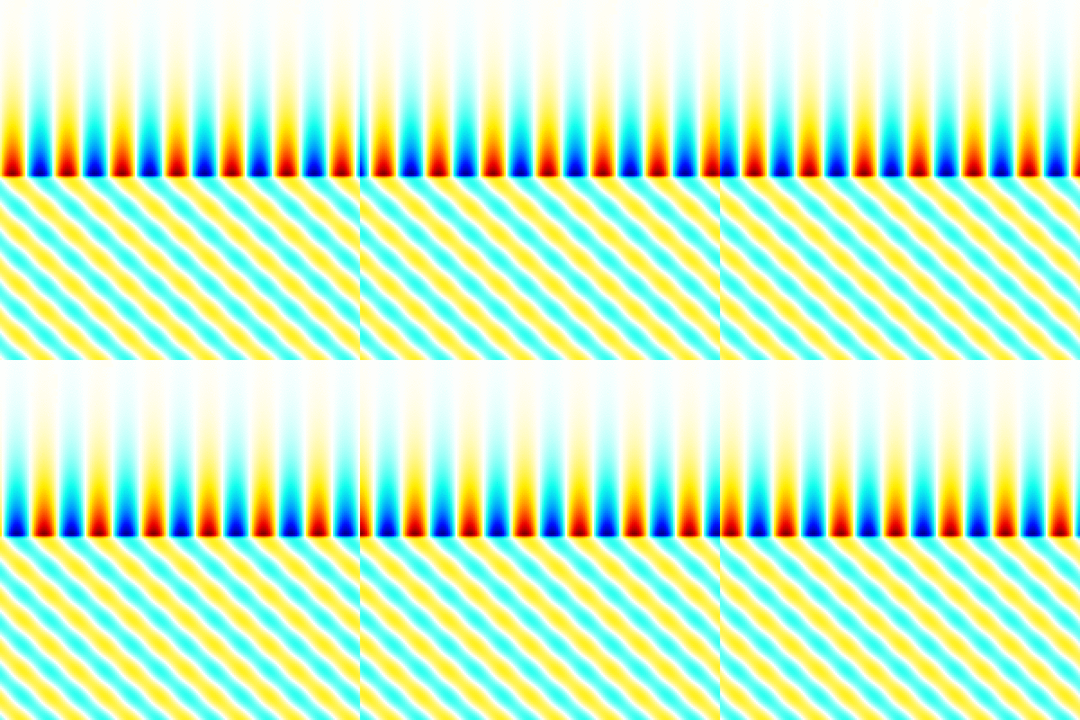
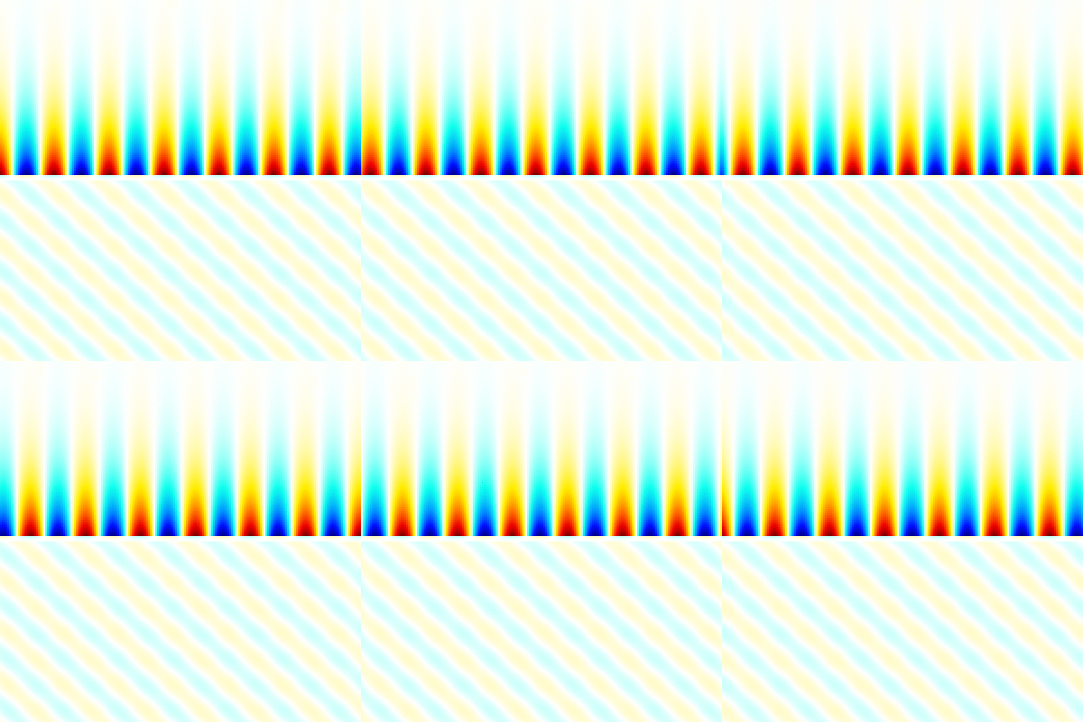
This is the electromagnetic field analysis program for multilayered substrate irradiated by a plane wave. The own developed numerical solution is used. Libpng is required.
-
type 'make' command to compile.
The executable example1.out, example2.out, example3.out, verification.out are created. The example1.out is the executable of source code example1.c, it shows a simplest example using "emf_multilayer". The example2.out is the executable of source code example2.c, it shows an analysis example of power reflection and transmission coefficients and electromagnetic field intensity distributions. The example3.out is the executable of source code example3.c, it shows an example of outputting the instantaneous value of the electromagnetic field as an image. The verification.out is the executable of source code verification.c, it shows the verification results using the boundary condition and Maxwell's equations. -
type './example1.out' with arguments of incident field datafile name and multilayer datafile name.
For example, './example1.out ipw.txt multilayer.txt'. The ipw.txt is the sample of incident plane wave datafile, p-polarized plane wave is defined in it. Please see the image of analysis model above for detail of incident angle and polarization state. The multilayer.txt is the sample of multilayer datafile, two-layered substrate is defined in it. The total number of layers is three by adding incident field layer (defined in ipw.txt). The example1.out outputs power reflection and transmission coefficients and electromagnetic fields at origin. -
type './example2.out' with arguments of incident field datafile name and multilayer datafile name.
For example, './example2.out ipw.txt multilayer.txt'. The datafiles are the same as example1.out. This executable calculates the power reflection and transmission coefficients and outputs them to text files, and also outputs the intensity distributions on z-axis in that state. The RTI_example2.png is the visualization result created by using Gnuplot script gscript_example2.plt (converted eps to png by using ImageMagick). -
type './example3.out' with arguments of incident field datafile name, multilayer datafile name and image output folder name.
For example, './example3.out ipw.txt multilayer.txt ./images'. The datafiles are the same as example1.out. This executable can reset the incdient angle at run time. For reset the incidient angle to 0.5(rad), type './example3.out ipw.txt multilayer.txt ./images 0.5'. This executable calculates instantaneous value of the electromagnetic fields, outputs them to png image files. The image files are output to the folder specified in the argument that is automatically created at runtime if it does not exist. Each image file has a name that indicates the cross section, field component and number of time steps (ex. xz_Ex_014.png). The color bar is output as color_bar.png in the same folder. The range of color bar in each cross section is output to the info.txt file (xy_info.txt for x-y plane). The xz_Ex.gif, yz_Ex.gif etc. are animated gifs that concatenate the png files, created by using the shell script gif_animation.sh. The example3.out is parallelized using OpenMP. The number of threads is controlled by the environment variable OMP_NUM_THREADS. -
type './verification.out' with arguments of incident field datafile name and multilayer datafile name.
For example, './example2.out ipw.txt multilayer.txt'. The datafiles are the same as example1.out. For reset the incidient angle to 0.5(rad) at run time, type './verification.out ipw.txt multilayer.txt 0.5'. This executable is to confirm that the obtained electromagnetic field satisfies the boundary conditions and Maxwell's equations.
Please see eml_src/pw_sp.h and eml_src/emf_multilayer.h for detail of functions. This example analyzes surface plasmon excitation irradiated with a p-polarized plane wave. The case of s-polarized plane wave is in the folder analysis_sample1. The case without metal layer is in the folder analysis_sample2.
This program use the own defined system of units (OSU), optimized for optics.
The system of units is defined as ( speed of light in vacuum ),
( permeability of vacuum ).
For the conversion from OSU to MKSA system of units, the unit of length in OSU is defined as
[m] in MKSA, the unit of power in OSU is defined as
[W] in MKSA. The conversions of base unit are follows.
,
,
,
,
,
.
Please see com_src/osu_mksa.h and com_src/osu_mksa.c for detail of conversions.
- The command-line driven graphing utility gnuplot
- The utilities for manipulating images ImageMagick
- The official PNG reference library libpng


