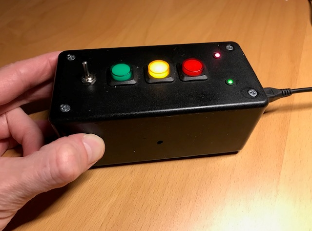
A push button control panel for the LED Alerter.
The LED Alerter is a separate project that allows you to control three LEDs using a custom web page. This project provides hardware control of the alerter's LEDs using dedicated pushbuttons. The alerter-client recieves feedback from the alerter and syncs to show the current LED color by illuminating the appropriate pushbutton. (It will sync even if the alerter is changed via its web page.) A toggle switch controls whether to activate the buzzer on the alerter. This device also includes a red power LED and a green LED that lights when a connection to the alerter has been established.
Here is the parts list:
- one 16mm Illuminated Pushbutton - Red Momentary
- one 16mm Illuminated Pushbutton - Yellow Momentary
- one 16mm Illuminated Pushbutton - Green Momentary
- one Mini Panel Mount SPDT Toggle Switch
- one Raspberry Pi Zero W or WH (with headers - easier)
- one 6" x 3" x 2" project enclosure like this or this
- two 3mm LED holders
- one 3mm red LED
- one 3mm green LED
- one angled micro USB panel mount cable
- one 150 ohm resistor
- four 220 ohm resistors
- one small breadboard PCB such as this
- some female - female jumpers and headers
- a micro SD card (at least 16GB) and a micro USB power supply
Here is the schematic for connecting everything together:
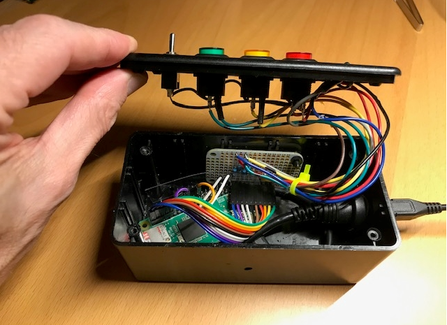
There are many options for wiring the project together. I used a small breadboard PCB to mount the resistors:
This project uses the balena IOT platform - you can sign up for a free account (up to 10 devices) here.
Create a new fleet in the balenaCloud dashboard, then download an image for the Pi Zero, making sure to enter your WiFi information. Burn the downloaded image to a microSD card and insert into the Pi Zero W. You now have a full OS that will connect to the internet and pull down this application once it is available.
Use the balena CLI to push this application from your local machine to balenaCloud using the fleet name you created earlier. Your device will now download and run the application.
You'll need to adjust a few settings before the alerter-client will work. First, in the "device configuration" in balenaCloud, change the "Define DT parameters" to "i2c_arm=on","audio=on" - basically eliminating the spi-on setting and turning off SPI. We do this because SPI will interfere with our use of GPIO 8.
In the "Device Variables" section of the balenaCloud dashboard, we'll need to add two variables:
- Set
LED_DEVICE_UUIDto the full UUID of your LED Alerter. You can find this value on the dashboard for the alerter device - Set
LED_DEVICE_ADDRESSto the local IP address of the LED alerter. The alerter will need to be on the same network as the alerter-client.
We use Node.js in this project. The onoff package to read the GPIOs, detect button presses, and create interrupts to act on the button presses. Socket.io Client is used to establish a websocket with the alerter and read/write data with the alerter.
Note that you can use different GPIO pins if you'd like, but you'll need to change the values in the buttonled.js code. Look out for other services that may be using a GPIO pin such as one-wire and SPI. If there is a conflict, you'll likely see an error such as Error: EBUSY: resource busy or locked, write. In addition, be aware that we can only detect button presses with GPIO pins that are held high by default, since our buttons connect the pins to ground by default. The defaults can be seen in Table 6-31 on pages 102 and 103 of the BCM2835 ARM Peripherals documentation.


