Moth Flight Control System
Electronic flight control system for the moth class sailboat to be mounted on a skiff developed by Polito Sailing Team
Explore the docs »
Report Bug
·
Request Feature
Table of Contents
The board we used is the STM32F411RE which offers the support for the Arduino Uno, and also for Arduino IDE.
The decision to keep using Arduino Libraries is because they are very well documented, easy to use and compatible for both the Arduino Uno and our STM32 board.
Here is the list of all libraries used for this project and the relative documentation:
- Adafruit BNO08x IMU Adafruit library
- MFRC522 RFID Arduino library
- PID Arduino library
- IWatchdog ST-Microelectronics library
- Servo Arduino library
Talking about ultrasonic sensors, we used HC-SR04 drivers, that allows us to trigger and read the sensors through 2 digital signals.
In particular, as you can see in our code, we need to set as high the trigger for 10us, after keeping it low for 2us, to make the sensor emit the sound wave.
The echo pin will immediately go up and will assume the low value when the wave will be received back. For all the other sensors and actuators, no additional driver has been used; the RFID reader is already communicating through SPI, the servomotor is driven by a PWM and the buzzer too. IMU uses I2C communication protocol.
This project aims at automatically regulate and control the height of the flight of a Moth.
Commercial products use mechanical elements to change the angle of the flap mounted below the drift, while the one on the rudder is directly regulated by the sailor. Our goal is to avoid the mechanical "measurement" of the height, using both ultrasonic sensors and an IMU, and automatically derive the right angle the foil must assume according to that.
In particular, our sensing system is composed of 3 ultrasonic sensors mounted one at the bow, and the other two at stern, to the left and right extremes of the skiff, and the IMU, that allows us to retrieve the spatial orientation of the boat. Taking into account the pitch and roll angles, we can properly weight the measured distances and find the height of the center of gravity of the boat.
First of all some offsets have been added to the ultrasonic measures to consider the boat as a flat surface on which the sensor are mounted, independently of the real position of the sensors on the z axis.
Then, the following offsets have been taken into account to retrieve the impact of the orientation of the boat on each measured data:

The output of the system is the angle the flap must assume in order to reach and maintain the TARGET height.
This has been obtained using two different PIDs, a more aggressive one, to quickly reach the target, and a conservative one, to smootly maintain the height.
The change between the two depends on the absolute difference from the target height: if this is above a defined THRESHOLD, we are using the first, otherwise we are using the second.
TARGET and THRESHOLD are then selected by the sailor between 3 different options for each parameter, just by approaching one of the two RFID cards to the reader.


(Wikipedia)
- STM32F4xx microcontroller
- 3 HC-SR04 waterproof ultrasonic sensors
- BNO085 IMU
- MFRC522 RFID reader
- servomotor (torque to be calculated according to flap and skiff dimensions/profile)
Follow the schematic below to setup the system:

IMU
| Board | Sensor |
|---|---|
| PB8(SCL) | SCL |
| PB9(SDA) | SDA |
HC-SR04
| Board | Sensor |
|---|---|
| PA0,PA1,PA4 | Trig |
| PB3,PB4,PB5 | Echo |
RFID
| Board | Sensor |
|---|---|
| PA8 | SS(SDA) |
| PA9 | RST |
| PB13 | SCK |
| PB14 | MISO |
| PB15 | MOSI |
Buzzer
| Board | Sensor |
|---|---|
| PC7 | + |
Servomotor
| Board | Sensor |
|---|---|
| PB10 | signal |
All the 3v3,5v and GND connections are not showed in the picture but have to be properly managed.

- Clone the repo
git clone https://github.com/alessandrolandra/PST_FlightControl.git
- Copy all the libraries contained in libraries in your respective Arduino folder
- Compile the stm32INOsketch and upload it on the board
Power on the device, calibrate the IMU, by performing the usual 8 in air around all the 3 different axes (a buzzer sound will let you know when the calibration is done) and mount everything in place. Use the wanted RFID card to change either the target height or the sensibility of the system (when to perform the switch between the two PID networks); click here for a quick demo. An example of how the system works and ties to maintain a certain target height is provided here.
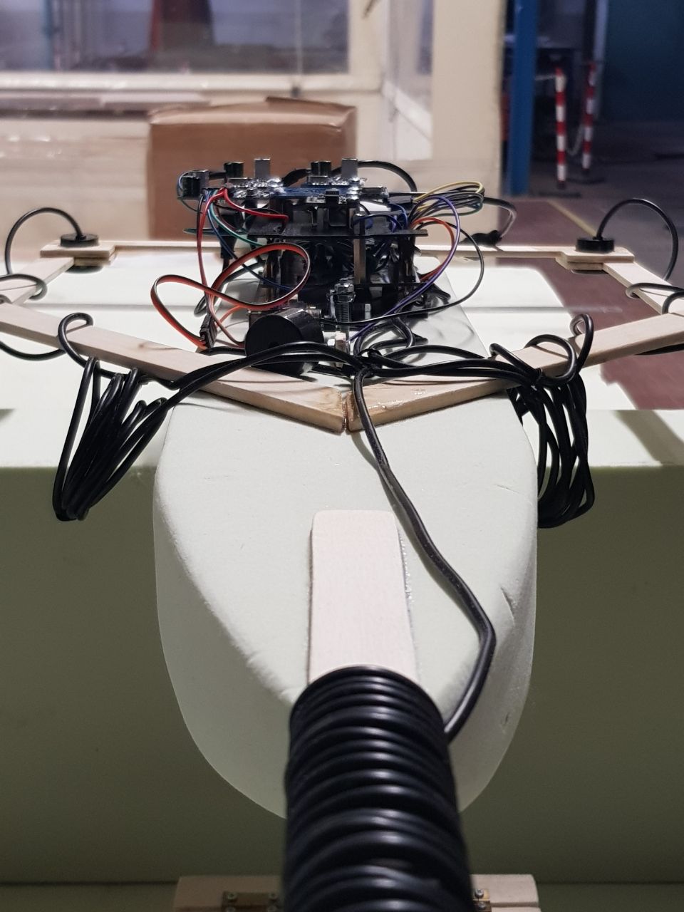
Below you can find some images documenting the different phases of work followed to build the entire system.


Contributions are what make the open source community such an amazing place to learn, inspire, and create. Any contributions you make are greatly appreciated.
If you have a suggestion that would make this better, please fork the repo and create a pull request. You can also simply open an issue with the tag "enhancement". Don't forget to give the project a star! Thanks again!
- Fork the Project
- Create your Feature Branch (
git checkout -b feature/AmazingFeature) - Commit your Changes (
git commit -m 'Add some AmazingFeature') - Push to the Branch (
git push origin feature/AmazingFeature) - Open a Pull Request
Distributed under the MIT License. See LICENSE for more information.
Luca Dalmasso, Omar Gai, Alessandro Landra
Project Link: https://github.com/alessandrolandra/PST_FlightControl