Plugins for use with VCV Rack virtual module synthesizer (https://github.com/VCVRack/Rack)
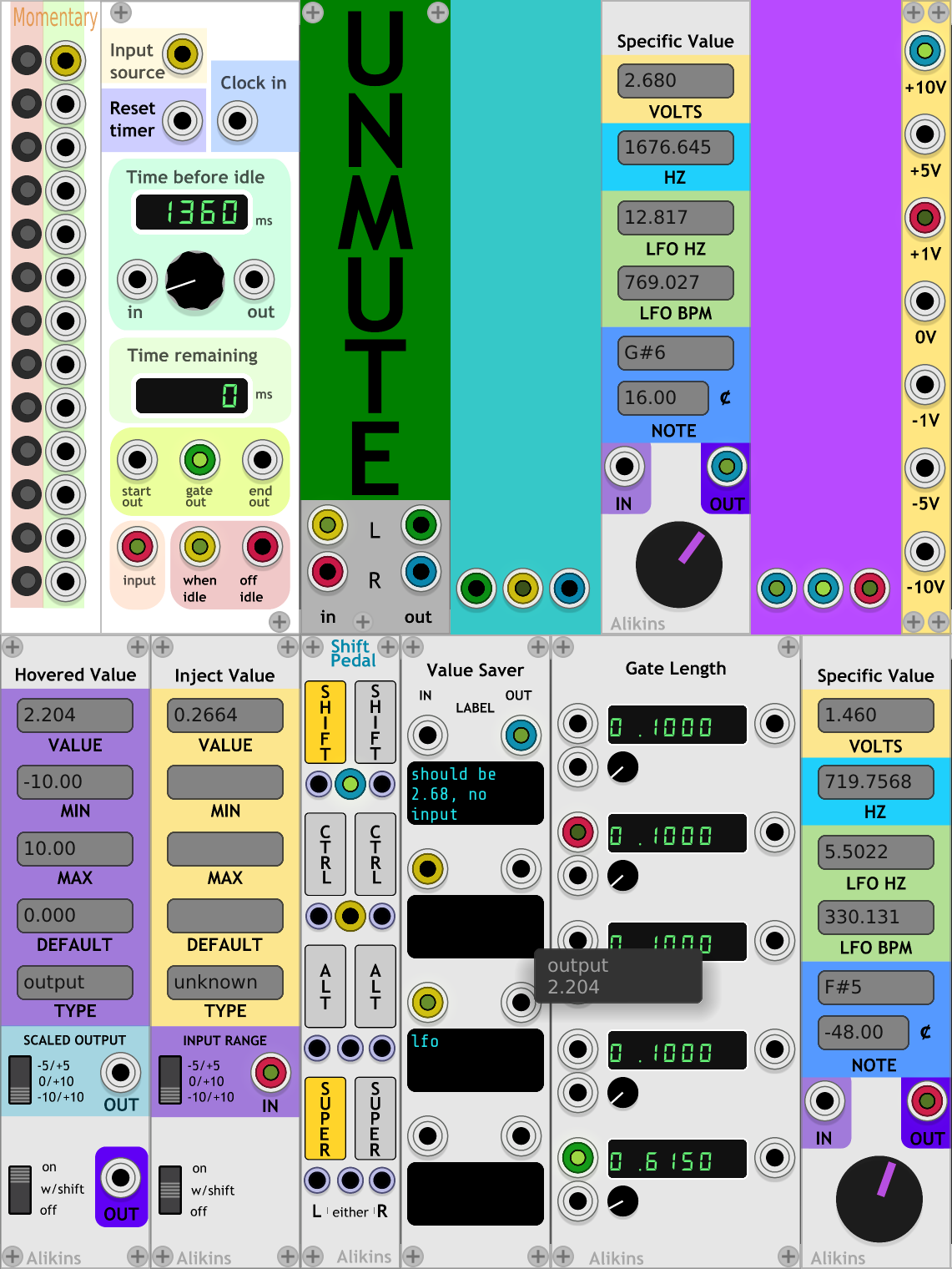
A controller module for outputting a specific voltage with displays and text input fields for:
- CV voltage,
- frequency (hz)
- note name ('C3' etc)
- note detune (cents)
- LFO (bpm)
- LFO (hz)
A specific value can be chosen with the knob widget or can entering values into any of the text fields.
Can also be used as a 'meter' displaying all of the above info for CV voltages fed into the IN input. This includes animation of the controller dial.
A specific note can be entered into the note text field.
The note format includes a note a letter and a positive or negative 'octave'.
Examples of valid formats include:
C4(C in the 4th octave)c3(note names can be upper or lower case)F#2(sharps are indicated by a '#' in the second field)Ab0(flats are indicated by a 'b' in the second field). Note that flats are currently converted to the equivalent sharp for display)C-2(The C six octaves below C4)
For notes that are slighty sharp or flat from a A440 tuning, the Cents display shows how the amount of detuning.
The LFO fields show the hz and bpm (beats per minute) corresponding to the current voltage, based on the standard at https://vcvrack.com/manual/VoltageStandards.html#pitch-and-frequencies
The HZ fields shows the hz corresponding to the current voltage for a VCO, based on the standard at https://vcvrack.com/manual/VoltageStandards.html#pitch-and-frequencies
Values can be typed into the text fields directly.
Left and Right arrow keys move the text cursor as normal when editing text.
To select all text to replace, use Ctrl/Command + 'a'.
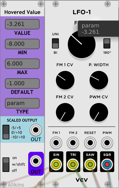
Hovered Value detects the widget or port that your cursor is hovered over and displays and outputs that value.
Use for figuring out what the range or value of an on screen widget.
If an LFO has multiple outputs, hover the cursor over each one to sample the output.
Use in combo with 'Specific Value' to quickly determine what note each of the outputs or controls is set to.
This module was inspired by a question and discussion on the Facebook 'VCV Rack Official User Group':
"Hi Folks, Just wondering, is it possible to see control parameter values in VCVRack?"
Simulate virtual circuit bending by hovering over any widget on screen and using it's CV output. Hook up the output to your clock bpm and wiggle the cursor across the screen.
Think of it as the Rack equivalent of using a Radio Shack Telephone Pickup to listen to a Sony Discman.
Tap into the machine and read it's mind. Investigate which modules have real resonance.
Worship the glitch.
There are two outputs. The lower purple 'OUT' output will send the raw param widget value. Note that this output may send values outside the normal -10V/+10V range.
The second output (light blue in 'Scaled Output' section') scales the output signal to one of three voltage ranges: -5V/+5V (BI), 0V/+10V (UNI), or -10V/+10V.
By default, 'Hovered Value' will how a tooltip showing the value above the hovered widget.
On the right click context menu, there is an option to disable this.
The bottom left 3way switch determines when the module runs.
The default is 'w/shift'. To read the value from a param, hold down 'Shift' key while hovering.
The 'On' option always reads the value from the currently hovered widget.
The 'out' output is currently not clamped or limited and may produce values outside of the -10/+10 V range.
The values of the hovered widget are sampled at the gui display rate, not at the audio or sound engine rate. This is typically ~60hz, so audio signals that are tapped will be reproduced with 'character'.
Inject Value is used to control the currently hovered widget with CV. Where 'Hovered Value' can read a param vaule, 'Inject Value' can write/change it.
The 'IN' port accepts a CV input and that value is sent to the currently hovered widget. This allows CV control of param widgets, even if the hovered module doesn't provide a CV input.
Hook up a CV source (like the output of a LFO) to the 'IN' and set 'INPUT RANGE' approriately (0/+10V for a 'UNI' LFO).
Select how/when 'Inject Value' is enabled. For example, choosing 'W/ SHIFT' on the bottom 3way switch.
Then move the cursor over any paramater widget like a knob, slider, or switch and hold down 'Shift'. The hovered widget will move to match the 'IN' value.
The input values are automatically mapped to the range of values supported by the hovered widget.
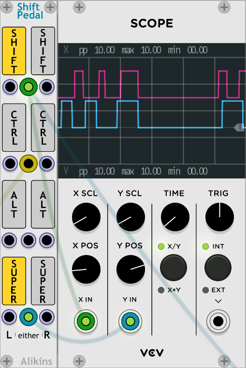
Note this can control widgets that normall don't have CV control. For example, the 'X SCL' knob on a Fundamental Scope module.
For widgets that normally expect a subset of possible values (like switch widgets for example), 'Inject Value' can end up setting the params to unexpected values. For a switch, this could be a float between 0.0 and 1.0, 1.512 for example. Some modules get a little confused if a param value is not exactly an expected value, so be cautious changing switch values with continuously variable inputs.
The values of the hovered widget are sampled at the gui display rate, not at the audio or sound engine rate. This is typically ~60hz, so audio signals that are tapped will be reproduced with 'character'.
'Shift Pedal' allows the 'Shift', 'Ctrl', 'Alt/Option', or 'Super/Windows/Command' keys to be used to generate gates.
For example, using the 'Shift' key to send a gate to control the sustain pedal param of a VST in Host.
For each modifier key supported, either the 'left', 'right' or 'either' can be used to control the gate output.
The 'left' modifier key will send a gate to the 'left' output port under each key in the ui.
The 'right' modifier key will send a gate to the 'right' output port under each key in the ui.
Pressing either the 'right' or 'left' version of the modifier keys will also send a gate from the middle 'either' output port.
The interaction with using the Core 'Midi-1' with the 'Computer Keyboard' drive is not great. The 'Computer Keyboard' driver ignores keyboard input if a modifier key is held, so using QWERTY midi input and then holding shift doesn't work as may be expected.
The last know value of a signal sent through 'Value Saver' will be remembered.
If you patch an input through it, it will remember and output the last value read from the input, even after the input is disconnected. Or on patch open, if the input value is a steady 0.0f it will output the value it was saved with.
Intended to help with cases like a Midi-1 CV output after module load but before anything is sent.
A label field is provided for each input for labeling what those inputs are used for.
An 'idle loop' inspired module for detecting when an input is idle and turns on a gate until it sees activity again.
If no input events are seen at "Input Source" within the timeout period emit a gate on "Idle Gate Output" that lasts until there are input events again. Then reset the timeout period.
Sort of metaphoricaly like an idle handler or timeout in event based programming like GUI main loops.
The timeout period is set by the value of the "Time before idle" param.
An "Input event" is a gate or trigger (or a CV or audio signal that looks sufficently like a gate or trigger).
After a input event, the Idle Gate Output will remain on until an input event is seen at Input Source. When there is an input event, the Idle Gate Output is turned off until the expiration of the "Time before idle" or the next "Reset idle".
If there is a "Reset timer" source, when it gets an event, the timeout period is reset. But unlike an "Input event", a "Reset timer" event does does not reset the idle status.
After "Reset time" event, the "Idle Gate Output" will remain on until an input event is seen at Input Source. When there is an input event, the Idle Gate Output is turned off until the expiration of the "Time before idle" or the next "Reset idle".
To use the eventloop/gui main loop analogy, a "Reset idle" event is equilivent to running an idle handler directly (or running a mainloop iteration with no non-idle events pending).
If a cable is hooked to the "Clock Input" then the pulse from the clock will determine with the idle time expires. When there is a clock pulse, if there were no input events since the previous clock pulse that is considered idle.
The "Time before idle" display will reflect the time since the last clock pulse. The "Time remaining" display will always show 0 for now, at least until it can predict the future.
The "Time input" expects a CV output between 0 and 10V. The voltage maps directly do the number of seconds for the idle timeout. Eg. a 5.0V CV to "Time input" sets "Time before idle" to 5000ms (5.0 seconds)
The "Time output" sends a CV output between 0 and 10V indicating the "Time before idle" value.
The "Time output" can be used to connect one or more IdleSwitch modules together so they share the same "Time before idle".
In "Clock input" mode, the "Time Output" will correspond with the "Time before idle" display until the time is over 10s, then the "Time output" will max out at 10V.
Once the idle timeout has expired, the "gate output" output will go high (+10V) and stay high until there are new input source events. ie, it turns on when there is no actively for the "Time before idle" length of time.
The "start out" output will send a +10V trigger at the start of idle, at the start of the "gate out" gate.
The "end out" output will send a +10V trigger at the end of idle, at the end of the "gate out" gate. This also corresponds to the same time as when a new "Input source" event is detected.
"start of" trigger == "we have gone idle" "end of" trigger == "we got input source events (activity) and am no longer idle.
The "Input" is switched between "When idle" and "Off idle" outputs based on idle state.
The "Input" port on the bottom left can be any input.
The "Input" will be routed to the "When idle" output if idle. Otherwise, the "Input" is routed to the "Off idle" output.
Note the "Input" does not have to be related to the input connected to the "Input source". "Input source" typically needs to be triggers or gates, but "Input" can be any signal.
Original intentional was to use in combo with a human player and midi/cv keyboard. As long as the human is playing, the IdleSwitch output is 'off', but if they go idle for some time period the output is turned on. For example, a patch may plain loud drone when idle, but would turn the drone off or down when the human played and then turn it back on when it stopped. Or maybe it could be used to start an drum fill...
The "Reset idle" input allows this be kind of synced to a clock, beat, or sequence. In the dronevexample above, the drone would then only come back in on a beat.
And perhaps most importantly, it can be used to do almost random output and make weird noises.
A CV controlled RGB/HSL color "blank" panel.
Supports selectable input ranges (0V to 10V or -5V to 5V) via right click context menu The color input mode is also selectable via the context menu.
Module is resizable.
A big mute button.
Use just before output to the audio interface module.
When clicked, will mute the output output. Will unmute on next click.
Easier/quicker than adjusting mixer levels, or system volume, or finding the tiny mute button on mixers.
A set of GUI buttons that send a +10V output while pressed.
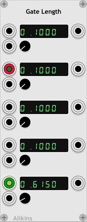
Change the length of a gate between 0 and 10 seconds. Length of gate is CV controllable.
This module was inspired by the question and discussion at: Facebook 'VCV Rack Official User Group':
Output some useful reference voltags: -10V, -5V, -1V, 0V, 1V, 5V, 10V
GPL-3.0-or-later. See LICENSE.txt


