(C) 2024 Alvaro Alea Fernandez
License under: CERN Open Hardware Licence Version 2 - Strongly Reciprocal
https://ohwr.org/cern_ohl_s_v2.txt
MORE INFO WILL BE ADDED, SOON
WARNING: As is design, is to tall (about 3mm) and do not allow the QL Case to be closed. BE AWARE
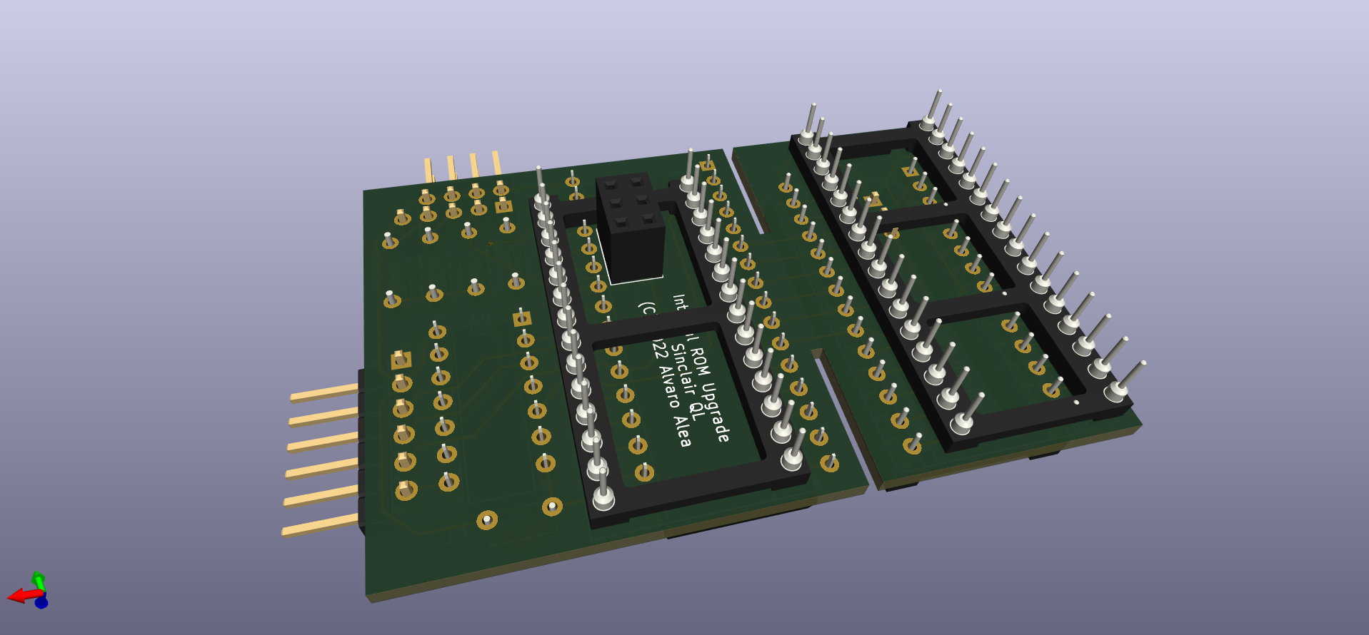
This board consist in 2 part (shall be 3, really)
A board that replace the 2 ROMS of the Sinclair QL. use a 39SF040 (512kb, 8x64kb, same chip that zx spectrum dandanator)
A board that allow to program the EEPROM Chip in a standar chip programmer.
A optional small board to glue in the outside of Sinclair QL (with dual side tape) and allow easy switch of the ROM, this board is not included, because I use a simple breadboard, with a 4 DIP Switch, and 6 cables that go to 5 back pines of the main board, the 4 pins in the border are not used.
Use female, turn-pin socket in the botton of the board, and 6 male pins on the adapter for the 2x3 conector in the middle, check the height of all.
J2 shall have 3 jumper 1-2, 3-4 and 5-6 for normal use, remove the 3 jumpers to program the chip.
J1 pins 1-2 are to enable the top 16Kb of memory, normally with Toolkit II, remove to use the external ROM Cartridge slot (for QIMSI, MICE and others) J1 pins 3-4,5-6 and 7-8 allow to select between 8 banks of ROM. Remove all J1 jumpers to program the chip.
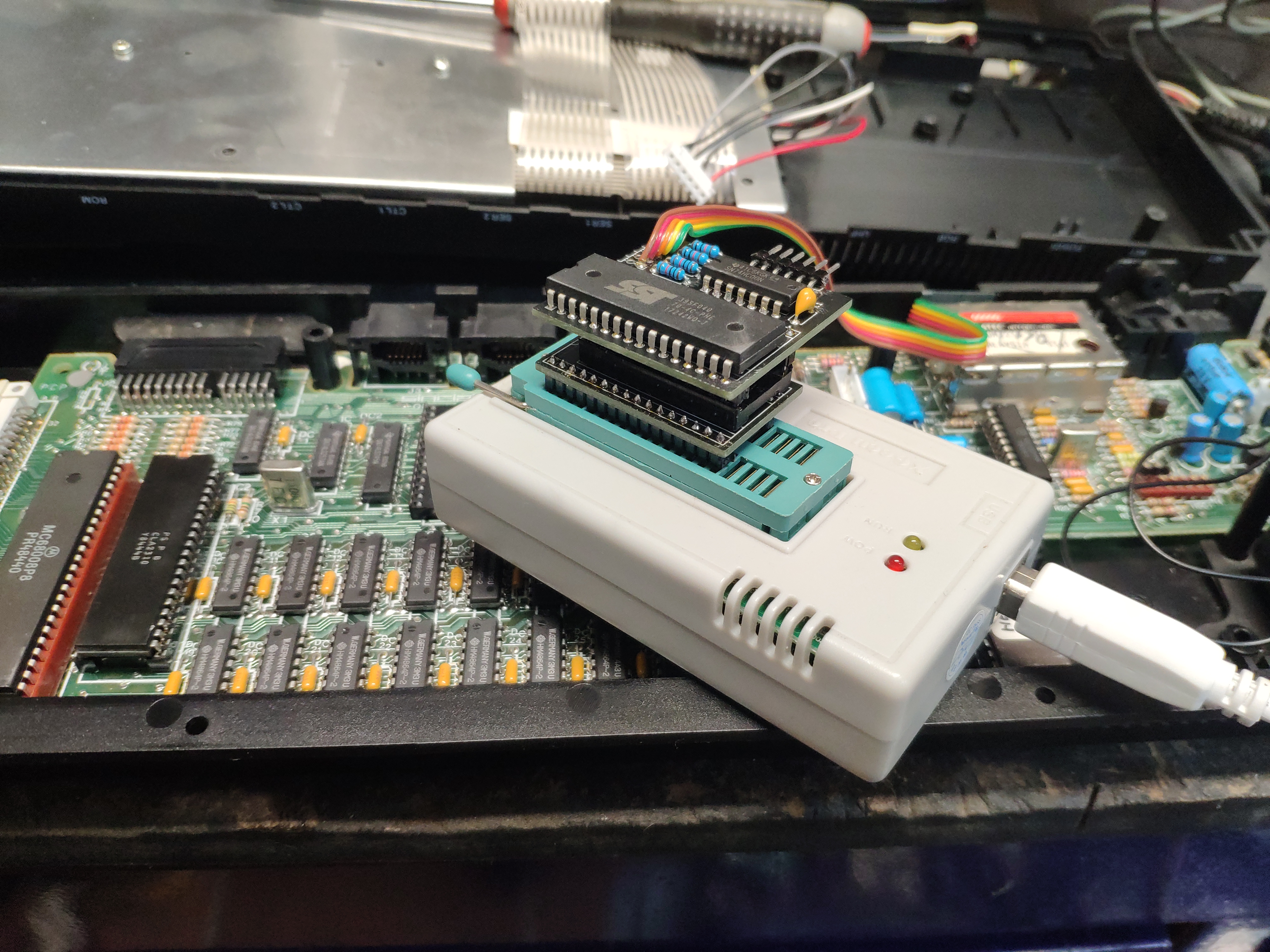
Insert the main board into the programer board, and insert both in the programer to program it.
The board installed on the QL:
Detail of the switch on back to select the ROM:
The adapter on programmer:
The board in the adapter ready to burn, check the J2 without jumpers.


