Team members: Andrii Yaroshevych, Pavlo Kryven
Board: STM32F411E-DISCO
- STM32CubeIDE version 1.11.0 is highly recommended
Note
You can use any other IDE, but you will need to configure it manually.
To compile the project in case of using other IDE, you will need to use the GNU Arm Embedded Toolchain. You can download it from here
If you are using STM32CubeIDE, you can use the following steps to compile and flash the project after opening it:
- Select the project in the Project Explorer
- Right-click on the project and select
Build Project - Right-click on the project and select
Run As->1 STM32 C/C++ Application
Clone the repository to your local machine using the following command:
$ mkdir ~/workspace
$ cd ~/workspace
$ git clone https://github.com/ucu-cs/stm32_5-1-kryven_yaroshevych
and open the project in STM32CubeIDE.
Connect the Discovery Kit to your PC using the USB cable and flash the project to the board as described in paragraph Compilation and Flashing
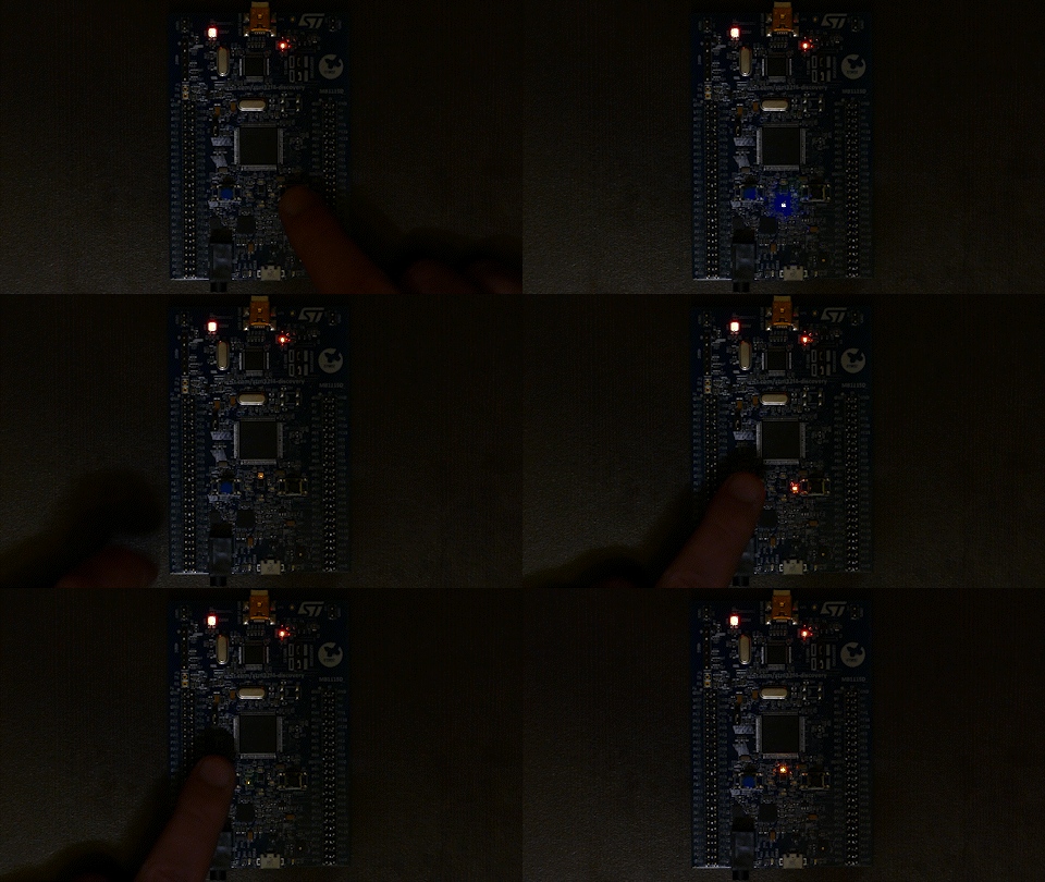
After flashing the project, the LEDs on the board will start to blink in a carousel fashion. The direction of the carousel can be changed by pressing the User button on the board.
Note
You can adjust the speed of the carousel by changing the value of the
PWM_DELAYconstant in themain.cfile.
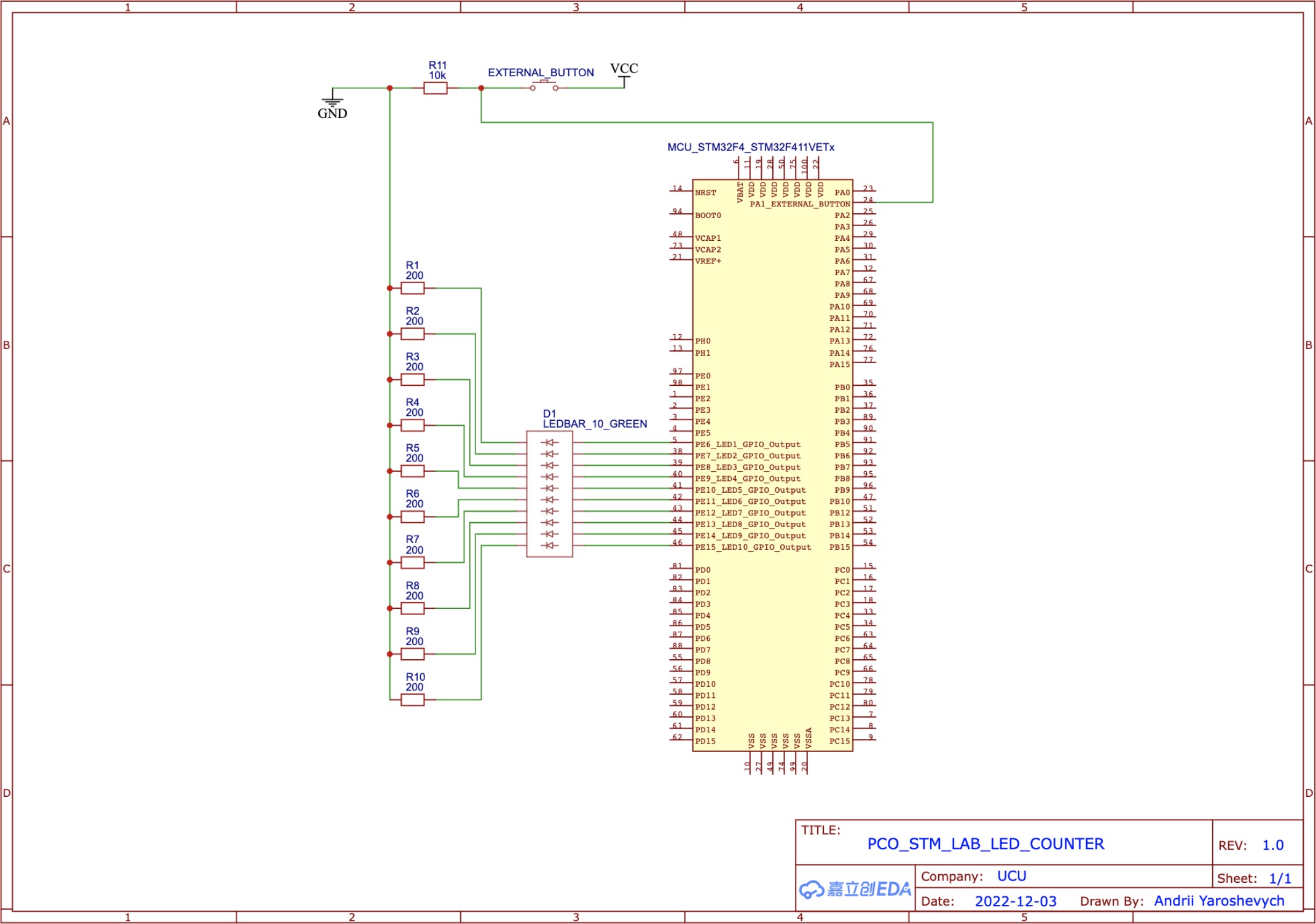
To complete this task, you will need to assemble the circuit shown below:
For better quality, you can see the pdf version of the schematic.
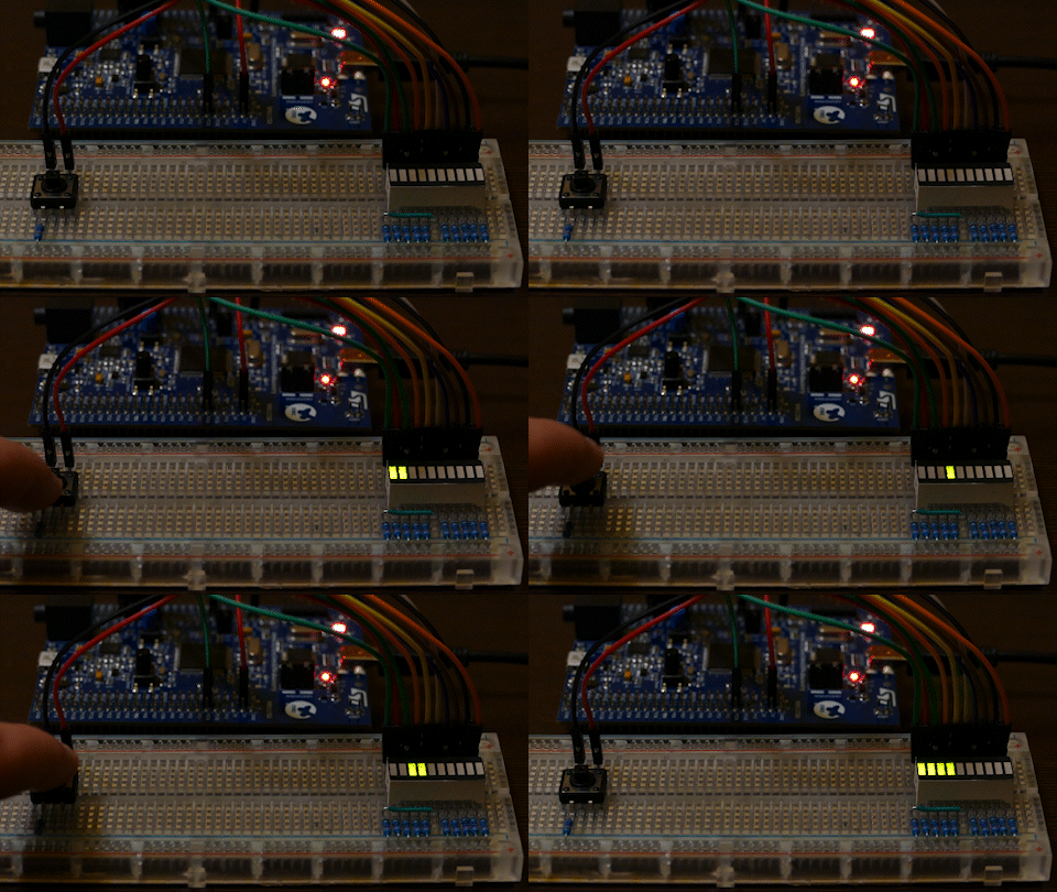
After flashing the project, the LEDs on the external LED bar will represent the number of times an external button was pressed in binary format.
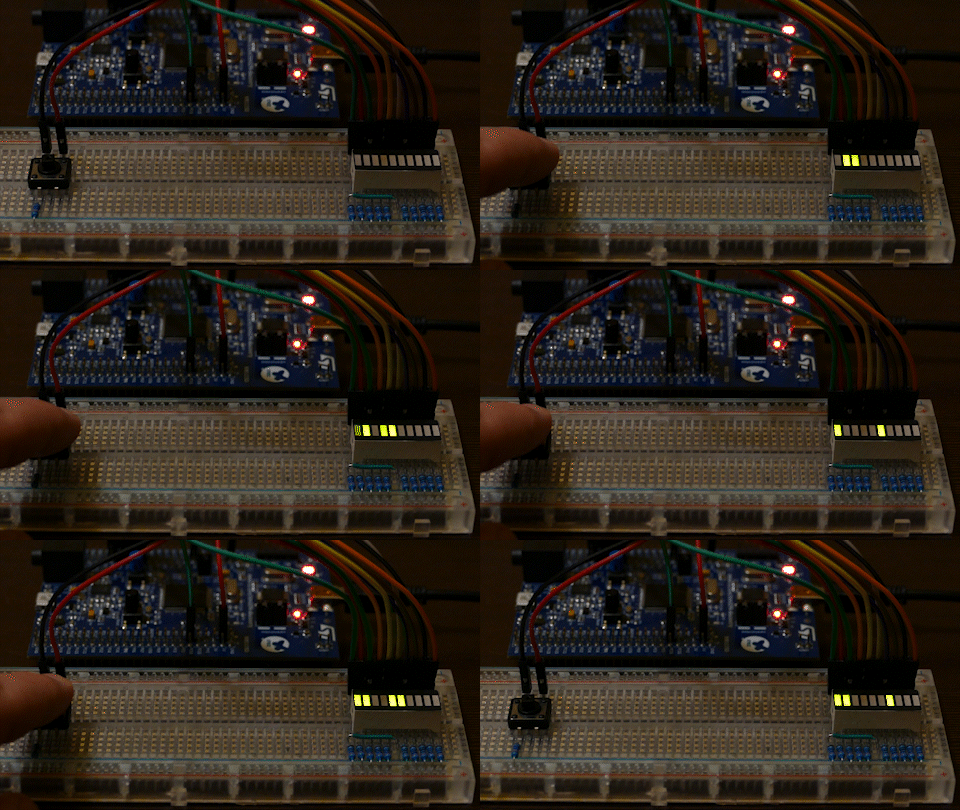
As additional functionality, if you hold the external button for 500ms counter will automatically increment by 1 every 100ms.
Note
This delays, respectively, can be adjusted by changing the values of the
HOLD_DELAYandAUTO_COUNT_DELAYconstants in themain.cfile.
To reset the counter, you can press the RESET button on the board.
Basic functionality:
Auto count functionality demonstration:
- Task 1: Use PWM to control LED brightness
- Task 2: Implement by relying on interrupts
- Task 1: Implement by relying on interrupts
The project was configured using the STM32CubeMX.
The configuration files can be found in the project directories - led_carousel/led_carousel.ioc and led_counter/led_counter.ioc.
Steps to configure the project using STM32CubeMX:
- Open STM32CubeMX
- Open the
.iocconfiguration file - For internal LED pins (
PD12-PD15) selectTIM4_CHxmode:PD12-TIM4_CH1PD13-TIM4_CH2PD14-TIM4_CH3PD15-TIM4_CH4
- Go to the
Pinout & Configurationtab and selectTIM4in theTimerssection:
Set all the channels to PWM Generation mode and select Internal Clock as the clock source.
Also, set the Counter Period value to 1000-1:
These steps are required to configure the PWM for the internal LEDs.
- On the
Pinout & Configurationtab, add user labels to the LED pins and User button:LED1-PD12LED2-PD13LED3-PD14LED4-PD15PUSH_BUTTON-PA0_WKUP
- Go to the
System Coretab and selectNVICsection:
allow the EXTI line0 interrupt to make the User button work.
Go to the GPIO tab and select the PA0_WKUP pin:
set the GPIO mode mode to External Interrupt with Rising/Falling edge trigger detection
- Go to the
System Coretab and selectRCCsection:
Set both HSE and LSE to Crystal/Ceramic Resonator.
Finally, generate the code and open the project in STM32CubeIDE.
- In STM32CubeMX, open the
.iocconfiguration file - For external LED pins (
PE6-PE15) selectGPIO_Outputmode on thePinout & Configurationtab:
- For external button pin (
PA1) selectGPIO_EXTI1mode:
also, give it a user label EXTERNAL_BUTTON.
- Go to the
System Coretab and selectNVICsection:
allow the EXTI line1 interrupt to make the external button work.
Go to the GPIO tab and select the PA1 pin:
set the GPIO mode mode to External Interrupt with Rising/Falling edge trigger detection
- Go to the
System Coretab and selectRCCsection:
Set both HSE and LSE to Crystal/Ceramic Resonator.
Finally, generate the code and open the project in STM32CubeIDE.
The MIT License (MIT)
Copyright © 2022. Andrii Yaroshevych, Pavlo Kryven


