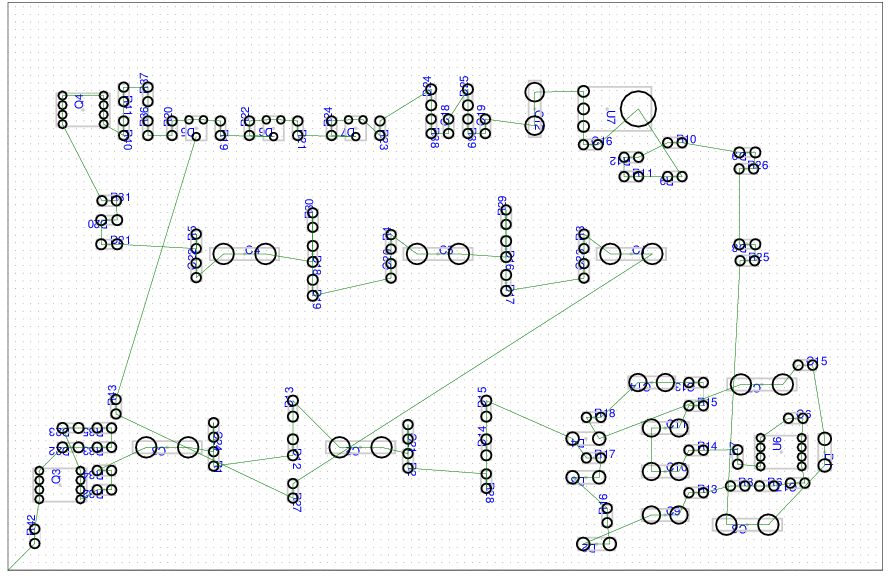
This code translates a KiCAD RPT file to G-Code for solder-paste dispensing and pick-and-place assembly on a 3D printer. You need a vacuum needle and solenoids for Pick'n place and a pressure pump and paste syringe for solder paste dispensing.
(TODO: describe hardware setup)
The setup for rpt2pnp is relatively simple: you place the board on the bed, and the tapes with opened 'lids' straight on the same bed. You tell rpt2pnp where the board is and the tapes, and it generates G-Code to do the operation.
There is not yet the concept of a feeder.
In general, you invoke rpt2pnp with an option to tell what to do and a
KiCAD rpt file.
To do any of paste-dispensing or pick-and-place operation, you need a configuration file with the origin of the board and the locations of the tapes.
The invocation without parameters shows the usage:
Usage: ./rpt2pnp [-l|-d|-p] <options> <rpt-file>
Options:
There are one of three operations to choose:
[Operations. Choose one of these]
        -d      : Dispensing solder paste.
        -p      : Pick'n place.
        -l      : Create BOM list <footprint>@<component> <count>
                  from parts found in rpt to stdout.

[Output]
        Default output is gcode to stdout
        -P      : Preview: Output as PostScript instead of GCode.
        -O<file>: Output to specified file instead of stdout
        -m<tty> : Directly connect to machine. Sample "/dev/ttyACM0,b115200"

[Choice of components to handle]
        -b      : Handle back-of-board (default: front)
        -x<list>: Comma-separated list of component references to exclude

[Configuration]
        -a          : Manual Adjustment step before sending to machine
        -t          : Create human-editable config template to stdout
        -c <config> : read such a config
        -D<init-ms,area-to-ms> : Milliseconds to leave pressure on to
                    dispense. init-ms is initial offset, area-to-ms is
                    milliseconds per mm^2 area covered.

[Homer config]
        -H          : Create homer configuration template to stdout.
        -C <config> : Use homer config created via homer from -H
Typically the workflow would be to create configuration via
homer ( https://github.com/jerkey/homer ).
Use the -h option to create a homer template
$ ./rpt2pnp mykicadfile.rpt -h > homer-input.txt
.. Then create a configuration with homer, and input it via the -C option.
With option -d or -p you choose the GCode output for dispensing or pnp:
 $ ./rpt2pnp -d -C config.txt mykicadfile.rpt -O paste-dispensing.gcode
 $ ./rpt2pnp -p -C config.txt mykicadfile.rpt -O pick-n-place.gcode
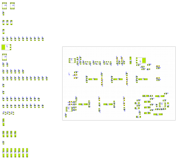
You can also create a PostScript view instead of GCode output with the -P
option; this is useful to visualize things before messing up a board :)
$ ./rpt2pnp -d -C config.txt mykicadfile.rpt -P -O dispense.ps
$ ./rpt2pnp -p -C config.txt mykicadfile.rpt -P -O pick-n-place.ps
You can directly connect to your machine by specifying the serial interface
with the -m option:
./rpt2pnp -d mykicadfile.rpt -m /dev/ttyACM0,b115200
If you supply the -a option, you can do interactive adjustment of the origin
of the board with cursor-keys; this looks roughly like this:
Find pad '2' of D3 (9.0, 9.1) and touch needle.
-----------------------------------------
Cursor keys: move x/y on bed
             U=needle up, D=needle down
Default:     0.1mm steps
+CTRL-Key:   1.0mm steps (FAST; careful when up/down)
-----------------------------------------
Delta: (-0.5, 48.1) ; top-of-board: 0.6
-----------------------------------------
Right now, the G-Code templates for processing steps is hardcoded in
constant strings in gcode-machine.cc - if your machine needs different
commands, change things there.
This is work in progress.
Missing features:
- an arbitrary rotated board.
- multiple boards
- not only tapes, but feeders
- semi-automatic registration using OpenCV
This describes the 'long' configuration created with -t. Typically you'll
use the shorter configuration created with -h. This long configuration might
go away as the short one seems to do its job (and also it might even more so
go away as we'll register things optically). So this section might go away :)
The configuration file consists of
- Board section. Describes board and its origin. (TODO: give sample component positions)
- Tape section: Describing the tapes that carry components, uniquely
identified by
<footprint>@<component>(e.g.SMD_Packages:SMD-0805@2.2k). Each tape has an origin and a spacing describing how far components are apart.
The template output creates a configuration including descriptions; you need to modify all the numbers to match what you have on the bed. It typically looks like this:
Board:
origin: 10 10 1.6 # x/y/z origin of the board; (z=thickness).

# Where the tray with all the tapes start.
Tape-Tray-Origin: 0 45 0

# This template provides one <footprint>@<component> per tape,
# but if you have multiple components that are indeed the same
# e.g. smd0805@100n smd0805@0.1uF, then you can just put them
# space delimited behind each Tape:
#   Tape: smd0805@100n smd0805@0.1uF
# Each Tape section requires
#   'origin:', which is the (x/y/z) position relative to Tape-Tray-Origin of
# the top of the first component (z: pick-up-height).
# And
#   'spacing:', (dx,dy) to the next one
#
# Also there are the following optional parameters
#angle: 0     # Optional: Default rotation of component on tape.
#count: 1000  # Optional: available count on tape

Tape: Capacitors_SMD:c_0805@C
origin:  10 20 2 # fill me
spacing: 4 0   # fill me

Tape: SMD_Packages:SM0805@2.2k
origin:  10 20 2 # fill me
spacing: 4 0   # fill me

