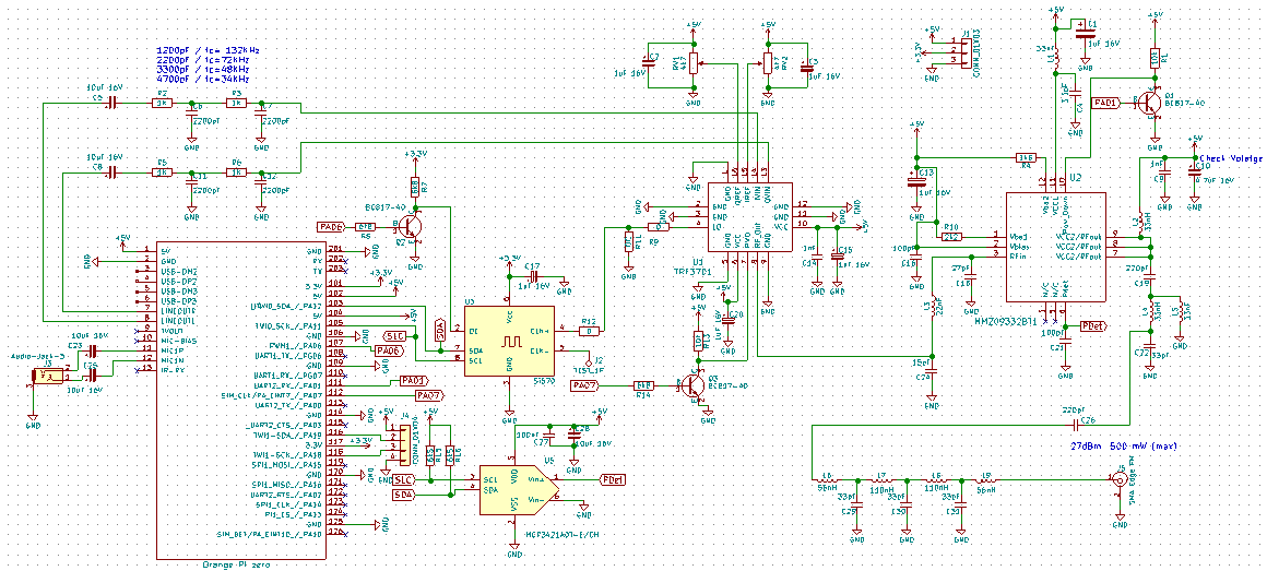
IQ Modulator for 2M generating IQ stream via Audio PCM codec as modelation and using I2C to controle the RF local oselator for the RF mixer. The modulated RF signal is the Amplified to about +27dbm. (estimated 500mW)
I2C Control for LO Local Osxelator with IQ moualtor RF amp and SAW and Ceremic output filters to antenna.

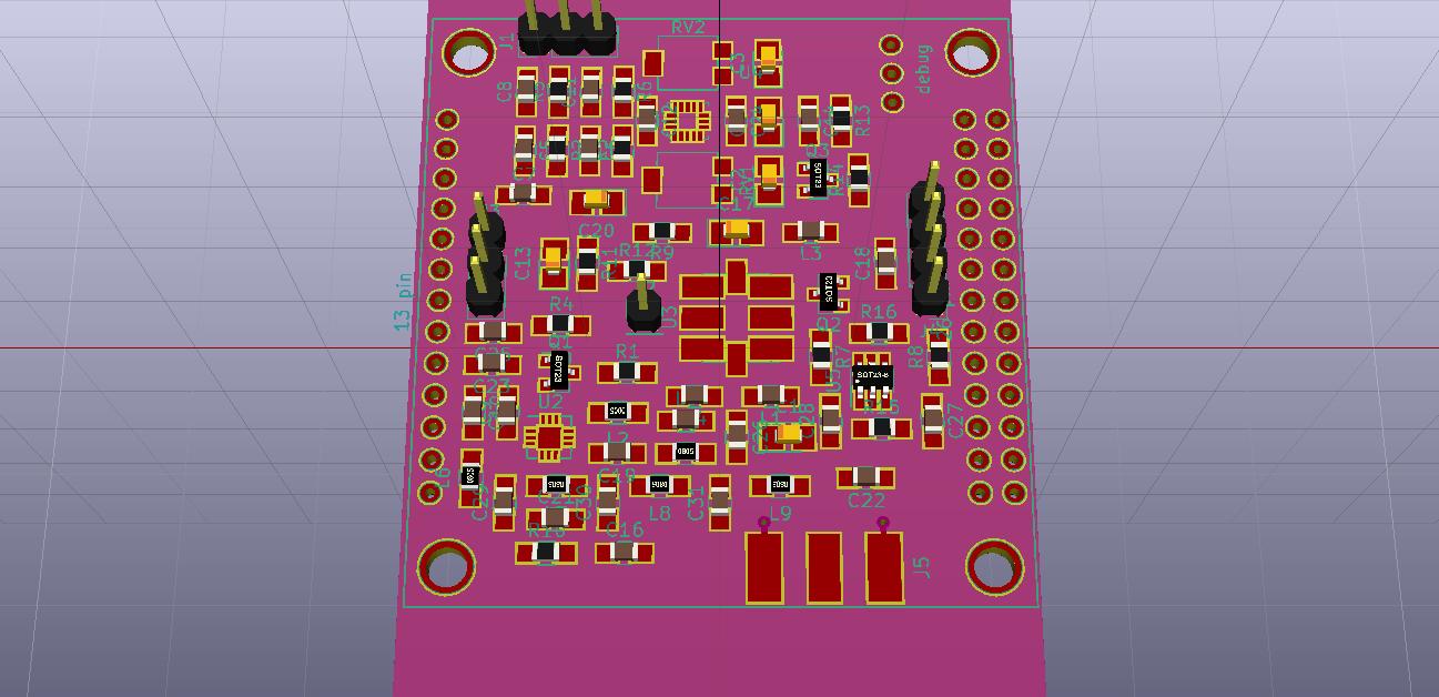
3d View

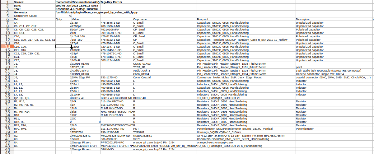
#Component list

I am considering using Orange Pi rather than Raspberry as it has build in Audio in and out with a smaller footprint
An another advantage of the Orange Pi is the additional USB ports witch I want to enable for the RTL dongle to be used as receiver.
The software concept was tested using gnuradio for transponder with a hackrf for TX and a rtl sdr dongle for RX.
I am still working on the telemetry witch works on its own but I need to combine it with Gnuraio transponder.
I have to telemetry modes at the moment CW send Calsign and cubesat name and settings. APRS 1200 FSK sending the status of transponder
Total power usage of board still needs to be calculated but my estimation with full power is 2w including Orange pi.
Power usage in sleep mode possibly 500mw
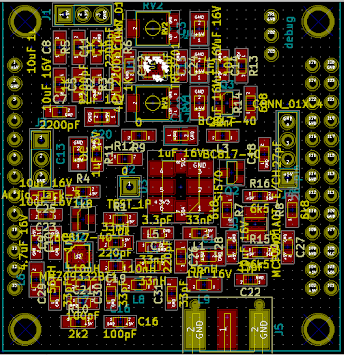
The PCB design was done in Kicad
This project is not compleet yet. (Almost done 12/06/2018)
My plan is to have it working by 15 July 2018.
The board V3 has the wrong pin configuration for U2 trf3701
I am now working on V4 ans need to get it working by 9 August 2018 for the BACAR6 baloon project.
- Real time clock (done) I had to remove the Real time clock as there is not enuf space on the PCB
- I2C pull up resistors (done)
- Maybe different 70cm filter. (2m filter was changed to discrete components pi 5 stage 40db down. The 70cm filter was removed as there was now space on the PCB)
- CS for ic's
- Temprature and Tx power measurementA/D. (The A/D was added using MCP3421A0T-E/CH and will read the power output of the MMZ09332BT1 30db power amp that should give us about +27dbm. This A/D reading can then be used to adjust the ALC level in the IQ stream)
- Battery and solar Voltage Monitoring (A/D) (I had to remove this as there was no space on the PCB Board)
- I forgot to add a 4k7 resistor to base of Q1. Fixed and is now added.
- Board placement redone thats why I have vertion 3 as I could not root all routes.
- Small Board to fit all components.
- My Pick and Place machien can not place components smaller that 0805.
The software for this Board will be in the following repository https://github.com/antonjan/Balloon-Transponder