Project: Kinematics Pick & Place
Steps to complete the project:
- Set up ROS Workspace.
- At first a ROS environment was setup. Cmd:$env produces the following info: ROS_ROOT=/opt/ros/kinetic/share/ros ROS_PACKAGE_PATH=/home/robond/catkin_ws/src:/opt/ros/kinetic/share GAZEBO_MODEL_PATH=/home/robond/catkin_ws/src/RoboND-Kinematics-project/kuka_arm/models
-After that, I created the top level catkin workspace(ROS Workspace) directory and a sub-directory named src -Next initialized and built the catkin workspace inside the src directory
-
Download or clone the project repository into the src directory of your ROS Workspace.
-
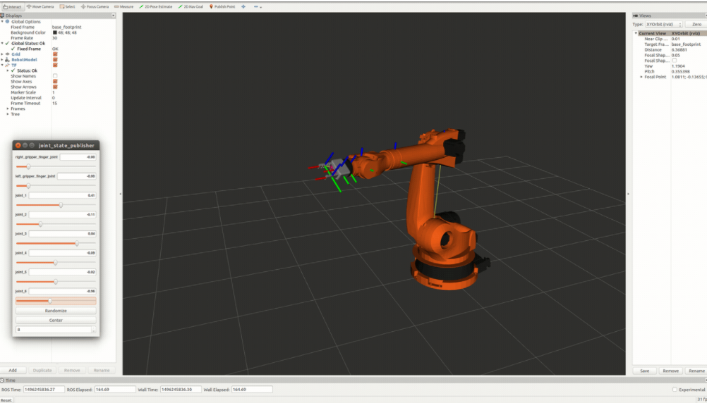
Experiment with the forward_kinematics environment and get familiar with the robot.
- Explored different tools such as Gazebo, Rviz and Moveit! to analyze forward kinematics and interact with Robot environment. -The goal of forward kinematics is to calculate the pose of the end-effector given all the joint angles, six in this case. Modified Denavit-Hartenberg parameter convention is used to associate reference frames to each link and complete the DH parameter table.
- Launch in [demo mode]. -First made sure the simulator is set to demo mode by checking that the demo flag is set to "true" in inverse_kinematics.launch file under ~/catkin_ws/src/RoboND-Kinematics-Project/kuka_arm/launch/
- Then launched the project by opening a fresh terminal and typing:
$ cd ~/catkin_ws/src/RoboND-Kinematics-Project/kuka_arm/scripts $ ./safe_spawner.sh
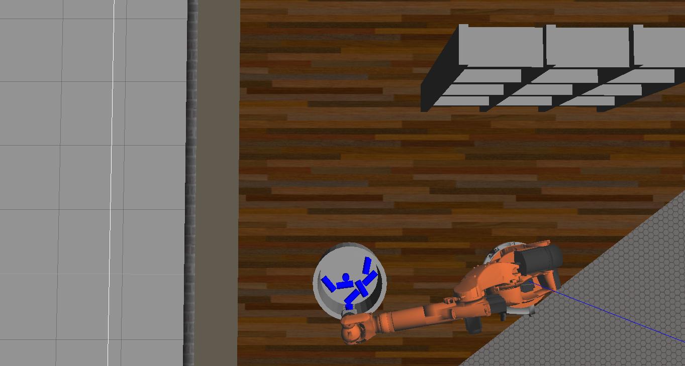
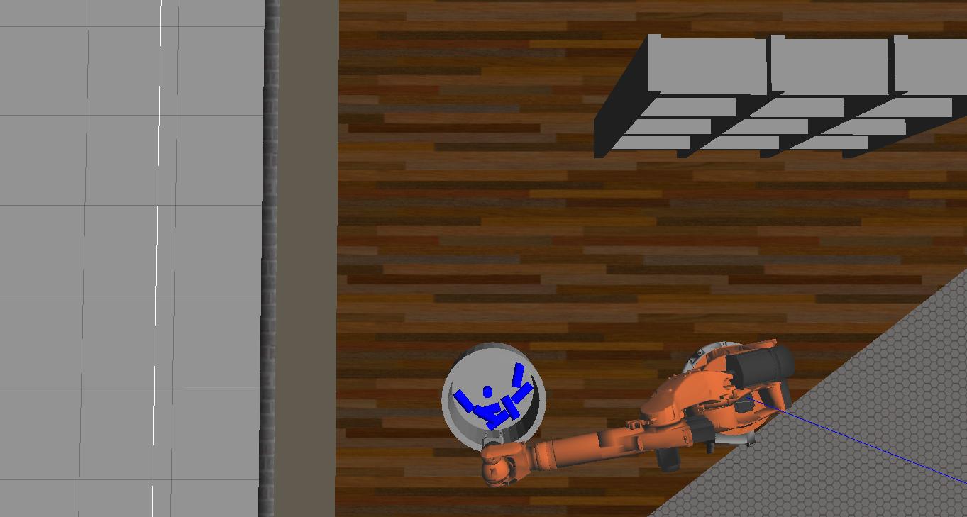
- Spawned target at different location changing spawn_location inside target_description.launch file
-
Perform Kinematic Analysis for the robot
-
Write
IK_server.pyfor Inverse Kinematics code.
Kinematic Analysis
1. Run the forward_kinematics demo and evaluate the kr210.urdf.xacro file to perform kinematic analysis of Kuka KR210 robot and derive its DH parameters.
-PDF named "DH_calc" attached to the submission folder shows how DH parameters were derived. -After that the URDF file was analyzed to find out the values of different parametrs.
2. Using the DH parameter table derived earlier, created individual transformation matrices about each joint.
In addition, also generated a generalized homogeneous transform between base_link and gripper_link using only end-effector(gripper) pose. The URDF file (kr210.urdf.xacro) was analyzed to find out the values of different DH parameters
Links | alpha(i-1) | a(i-1) | d(i-1) | theta(i)
--- | --- | --- | --- | ---
0->1 | 0 | 0 | 0.75 | q1
1->2 | - pi/2 | 0.35 | 0 | -pi/2 + q2
2->3 | 0 | 1.25 | 0 | q3
3->4 | -pi/2 | -0.054| 1.50 | q4
4->5 | pi/2 | 0 | 0 | q5
5->6 | -pi/2 | 0 | 0 | q6
6->EE | 0 | 0 | 0.303| 0
3. Decouple Inverse Kinematics problem into Inverse Position Kinematics and inverse Orientation Kinematics;
doing so derive the equations to calculate all individual joint angles.
Since the last three joints in our robot are revolute and their joint axes intersect at a single point, we have a case of spherical wrist with joint_5 being the common intersection point and hence the wrist center.
This allows us to kinematically decouple the IK problem into Inverse Position and Inverse Orientation problems as discussed in the Inverse Kinematics theory lesson.
Since we have the case of a spherical wrist involving joints 4,5,6, the position of the wrist center is governed by the first three joints,we can obtain the position of the wrist center by using the complete transformation matrix we derived in the last section based on the end-effector pose. Following is a snippet how it was implemented into the code:
#Wx,Wy,Wz=wrist positions
Rrpy=rot_z(yaw)*rot_y(pitch)*rot_x(roll)*R_corr
        nx=Rrpy[0,2]

        ny=Rrpy[1,2]

        nz=Rrpy[2,2]

        Wx= px-0.303*nx

        Wy= py-0.303*ny

        Wz= pz-0.303*nz

	##theta1
        theta1=atan2(Wy,Wx)
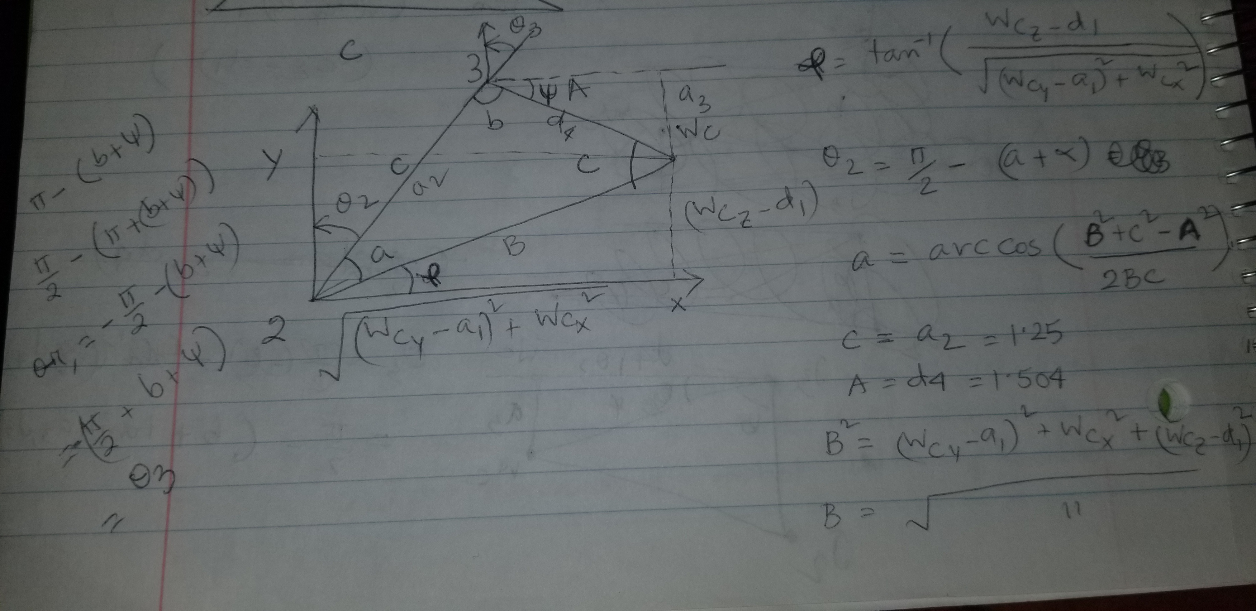
##SSS triangle for theta2 and theta3
        side_a=1.501

        side_b=(pow(sqrt(Wx**2+Wy**2)-0.35),2)+pow((Wz**2-0.75),2))

        side_c=1.25

        angle_a=acos((side_b**2+side_c**2-side_a**2)/(2*side_b*side_c))

        angle_b=acos((side_a**2+side_c**2-side_b**2)/(2*side_a*side_c))

        angle_c=acos((side_b**2+side_a**2-side_c**2)/(2*side_b*side_a))

        ##theta2
        theta2=pi/2-angle_a-atan2(Wz-0.75,sqrt(Wx**2+Wy**2)-0.35)

        ##theta3
        theta3=pi/2-(angle_b+0.036)  #0.036 accounts for sag in link4 0f -0.054m
##Evaluating WC rotation matrix at theta1, theta2 and theta3
        R0_3=T0_3[0:3,0:3]

        R0_3=R0_3.evalf(subs={q1:theta1,q2:theta2,q3:theta3})

        ##theta 4,5,6

        R3_6=R0_3.inv("LU")*Rrpy

        theta4=atan2(R3_6[2,2],-R3_6[0,2])

        theta5=atan2(sqrt(R3_6[0,2]**2+R3_6[2,2]**2),R3_6[1,2])

        theta6=atan2(-R3_6[1,1],R3_6[1,0])
Also, attached pdf "IK_calc" contains drawing to derive the relation between joint angles and wrist center position co-ordinates
Project Implementation
1. Wrote the IK_server.py file with properly commented python code for calculating Inverse Kinematics based on previously performed Kinematic Analysis.
Here I'll talk about the code, what techniques I used, what worked and why, where the implementation might fail and how I might improve it if I were going to pursue this project further.
Technique Used:
Following are the steps used in the IK code that would provide the necessary joint angle to perform pick and place operation:
1.Create symbols for joint variables
2.Create DH Parameter dictionary
3.Define Modified DH Transformation matrix
4.Create individual transformation matrices
5.Find the R_corr, which is the correction rotational matrix that resolve the difference of Gripper Link in URDF vs DH Convension
6.Extract end-effector position and orientation from request
        # px,py,pz = end-effector position
        # roll, pitch, yaw = end-effector orientation
-
Define functions for Rotation Matrices about x, y, and z given specific angle.
-
Calculate joint angles using Geometric IK method
9.Populate response for the IK request
What worked and why:
While using debugging forward kinematics by comparing the gripper_link position with that of the output from my code, I found that the x-y-z position at my code is pretty close to joint_state_publisher window output. Also, using IK_debug.py code I found the error for the wrist positions ang joint angles are close to zero at different test cases
Where implemantation might fail and scope of improvements:
The code might not be optimized for low speed proccessor and it could be improved for fast rendering.


