Team 11: Arushi Mittal (2019101120), Kunwar Shaanjeet Singh Grover (2019101059), Manasvi Vaidyula (2019101012), Mehul Mathur (2019101046), Pooja Desur (2019101112)
- Abstract
- Introduction
- Problem Statement
- Purpose Of The System
- System Overview
- Design Document
- System Requirements
- System Specifications
- Stakeholders
- Main Components
- Microcontroller
- Ultrasonic Sensor
- OneM2M Server
- Dashboard
- Conceptual Flow of Development
- Choosing the Microcontroller
- Choosing the Sensors
- Developing the Algorithm
- Choosing OneM2M
- Integration
- Security
- Database
- Conceptual Flow Of The Process
- Set Up
- Detecting Obstacles
- Navigation
- Mapping
- Dashboard
- Entity Interaction
- Microcontroller and Sensors
- Microcontroller and Motor Drivers
- Power Sources
- Microcontroller and OneM2M
- OneM2M and Dashboard
- Operational Requirements
- System Needs
- UI Design
- Analytical System
- IoT Project Components
- Hardware Components
- Communication
- Software Components
- Data Handling
- Integration
- Data Visualization
Mapping and localization is a pertinent problem in the field of mobile robotics, and requires extensive use of intelligent, durable, reliable machines that are capable of traveling and navigating in an unknown environment. These robots enable us to gain deeper insights about environments where it may be too difficult or impossible to send humans, such as the unexplored areas of the ocean, cave systems, or even outer space. In this document, we outline the technical details of the implementation of this robot along with the ideas used while devising the design of the various facets of the project. In addition, we have included a user document section to share details with the end users on how they can make the most out of this project.
The purpose of this developer document is to familiarize the reader with all technical, non-technical and design aspects of the obstacle avoiding course project as part of the Embedded System Workshop course project presented by Team 12. It details the processes involved in the completion of this project, explains all the choices made during the design of the system and the scope of the system. This document serves to provide a basis for understanding and continuing this work, as well as an instruction manual for users who may use this system.
The aim of this project is to build a fully functional, autonomous, mobile robot that can detect and avoid obstacles, and automatically correct its course by navigating in an unknown environment. Users are always in contact with the robot via a web-based dashboard equipped with various graphs to share the robots metrics with the users. This robot uses ultrasonic sensors to gauge the distance, along with a OneM2M server to store and process data, and a JavaScript-based dashboard to display the data. The agenda is to prioritize efficiency, security and optimum functionality.
The primary purpose of this robot is to navigate unknown environments and share data with the users for further analysis about this environment. The robot delivers data about the position, orientation, number and frequency of obstacles, and other information that allows humans to gain a descriptive overview of this environment. It is similar to localization and mapping functions from mobile robotics on a simpler scale. This robot can be sent to map or navigate environments deemed as unsafe or inaccessible for humans, or simply environments for which humans need timestamped, measured information. On a more simple scale, the robot can also be used to transport objects, or travel between two locations (eg: as a robot vacuum cleaner). The project was built keeping in mind the versatility of the robot, with the intention to make it usable for as many applications as possible with minimal need for customization.
The primary component of the system is an ESP32 board that controls the movements of the robot, along with a set of batteries for power, and an ultrasonic sensor for detecting how far obstacles are. All these components are encased in a chassis with a motor and three wheels, comprising the body of the robot and facilitating movement. The data collected by the robot is then encrypted sent to a secure OneM2M server, from where it goes to a web-based JavaScript dashboard, where users can log in securely and view various graphs that display multiple metrics collected by the robot, plotted in the form of graphs with respect to time. All the shared data is stored on a dedicated MongoDB Cloud database. The system allows users to control the point where the robot starts and stops moving. The components are designed to work together efficiently, while ensuring the system is robust, secure and durable.
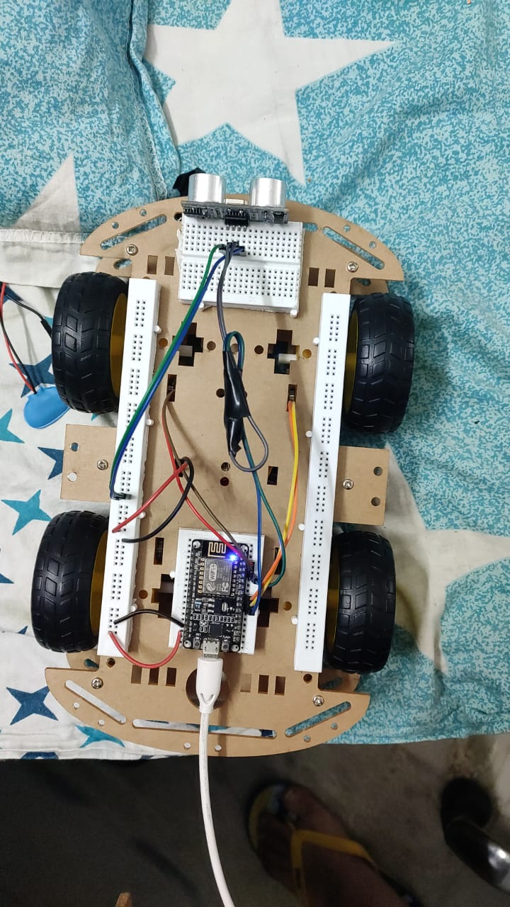
Robot Image
The system must be capable of connecting to the internet for sharing information collected during navigation. In addition, it must be able to measure the distance between itself and various obstacles, and to move and change direction to avoid those obstacles. It is essential for the system to be able to deal with slightly uneven terrains, and densely populated areas with many obstacles. Users must be able to send signals to the robot to start or stop moving.
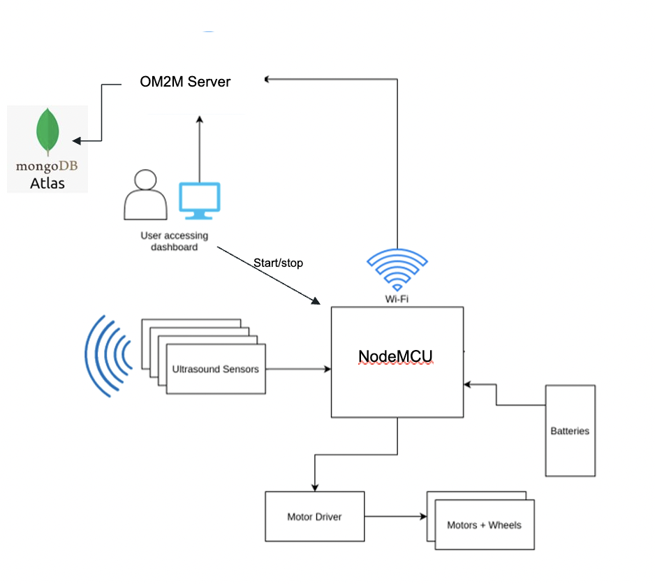
The ESP32 microcontroller is connected to an HC-SR04 ultrasonic sensor, an L298 motor driver, and 9V batteries, all connected to each other via wires, and placed carefully inside a chassis equipped with two motors and three wheels. The data from the microcontroller is shared with the OneM2M server and the web-based dashboard using encryption. The information for the dashboard is stored on a cloud-based MongoDB database for longer-term storage.
The microcontroller is used to analyze the distance data so the next steps for navigation can be assessed. The code for navigation is written in Micropython.
The ultrasonic sensor is used to gauge the distance between the robot and any obstacles in its path.
The motor driver is used as an interface between the wheels and motors of the chassis, and the movement instructions from the microcontroller. Depending on the output from the microcontroller, the wheels move forward, backward, left, or right.
The batteries are used to power the system and ensure that with timely battery replacement, it works without reliance on any external power source.
The chassis is used to contain all the components that make up the computational portion of the system as well as the body of the robot, helping with functions such as transportation and changing directions.
The database is used to store all the data about location, frequency of obstacles and direction change for future analysis and long-term storage of the collected data.
The primary stakeholders with respect to this project are the users who gain information about an environment without having to perform exploratory analysis themselves. Since the system can be thought of as an invasive entity in an unknown environment, the living and non-living entities within the environment being explored by the robot are secondary stakeholders since the robot is a part of their surroundings and collects information about it. If any information is known about the inhabitants of the environment, it is a good idea to monitor the impact of the system on those inhabitants.
- Microcontroller: The ESP32 board is used to connect all the components, collect information about the obstacles from the sensor, and to share information about movement, orientation and navigation with the motor drivers.
- Ultrasonic Sensor: The HC-SR04 sensor is used to collect data about the distance between the robot and any obstacles in front of the robot, and this data is used by the microcontroller to make decisions about its movement.
- OneM2M Server: Sensor data is collected, encrypted and uploaded to the OneM2M server in real-time in order to make data as relevant and secure as possible. This reduces the load on the device and allows for storage and computation in the cloud instead of on the device.
- Dashboard: The dashboard makes all the collected data usable for further inference. All the collected information is displayed in the form of graphs and images for easier comprehension. Users must use secure credentials in order to login, and these credentials are always encrypted in order to ensure secure access to the data collected. The dashboard also enables users to send commands to the robot to start or stop movement.
Component Diagram
The development of the system involved extensive literature review and research into ways for building such a system in a secure, robust, effective and cost-efficient manner, while ensuring that it is portable, durable and multi-purpose. We also researched the various components to ensure they satisfied the requirements of the project, and could be used to scale the system up or use it in different contexts or add new functionalities.
-
Choosing the Microcontroller
ESP32 was chosen instead of Arduino Uno because in addition to costing less, this board has Wi-Fi and bluetooth functionality that can allow it to communicate with other devices as well as the servers. This makes it more scalable and extensible for future projects compared to ESP8266. Additionally, it is very easily available.
-
Choosing the Sensors
The HC-SR04 sensor allows for non-contact distance measurement, ensuring the robot does not come into contact with any of the obstacles. It provides very accurate measurements using ultrasound without any image processing, ensuring that onboard processing is kept to a minimum for maximal efficiency.
-
Developing the Algorithm
Our priority for the algorithm was speed, efficiency, and prevention of any kinds of malfunctioning. We devised an algorithm that minimizes the number of sensors, and uses a single sensor for all four directions. The robot moves forward until it encounters an obstacle, following which it checks left, right and backwards in that order if the directions preceding them are unavailable. If the direction is available, the robot simply moves in that direction.
-
Choosing OneM2M
OneM2M ensures that the onboard processing and storage capabilities are increased, while allowing for scalability, integration with larger systems, greater processing, and security of the information transported. Moreover, it allows for visualization of the data on a separate web dashboard.
-
Integration
We attempted to break the system down into small, manageable components and added them together to make sure they worked well together. We verified the algorithm by running the code by simulating situations instead of directly testing it. We added all the components on the breadboard to verify that the sensors were working and sharing data properly. We also checked the motor and drivers were working with the power source to facilitate movement. The dashboard and server were also configured and checked independently with various requests sent back and forth before integrating all the parts one by one until we had a functional system.
-
Security
We added layers of encryption to ensure all the data was secure. We added encryption to the data while it was sent from the OneM2M server, as well as when it was sent to the dashboard. We also added secure credentials for logging into the system using javascript. All credential data is encrypted to prevent any misuse.
-
Database
We chose a robust MongoDB Cloud database to ensure that all the information is stored in a secure manner on the cloud which makes it difficult for unauthorized people to access. Additionally, it satisfies all the constraints of databases with respect to integrity, while ensuring
-
Set Up
The robot is assembled and placed in an unknown environment where it has at least one direction to move in, and a reliable connection to the server. The robot begins to move forward.
-
Detecting Obstacles
The ultrasonic sensor at the front of the robot scans the path continuously and sends a signal when an obstacle is closer than 0.25 meters. This value can be easily altered depending on the requirements.
-
Navigation
Upon encountering an obstacle, the robot turns left and gauges the distance. If it’s a viable direction, the robot continues to the left. If not, it checks right and repeats a similar process. If neither is a viable option, the robot begins to move backward.
-
Mapping
The robot continuously scans for obstacles and records its movements in various directions. At each moment in time, the number of obstacles and direction chosen is recorded and shared with the OneM2M server and encrypted for safety.
-
Dashboard
All the encrypted data is sent to a web-based dashboard that has a login functionality to ensure authenticated access to the data. Users can log in through secure, encrypted credentials and view graphs of the directions and obstacles. All the information is stored in a cloud-based MongoDB database where it can be stored for a longer time period in a secure manner ensuring security and privacy of the data. Additionally, users can use the dashboard to send commands to the robot to start or stop moving.
Code Flow Diagram
-
Microcontroller and Sensors
The microcontroller is integrated with the ultrasonic sensor through the breadboard with the intention of measuring the distance from the nearby obstacles. This input is received in real-time.
-
Microcontroller and Motor Drivers
The microcontroller is integrated with the motor driver through the breadboard in order to send signals from the microcontroller to the motors to guide movement and direction.
-
Power Sources
The robot chassis consists of various components connected to 9V batteries to ensure there is a constant source of internal power without any reliance on external sources. This ensures that the robot does not fail even in the absence of power sources.
-
Microcontroller and OneM2M
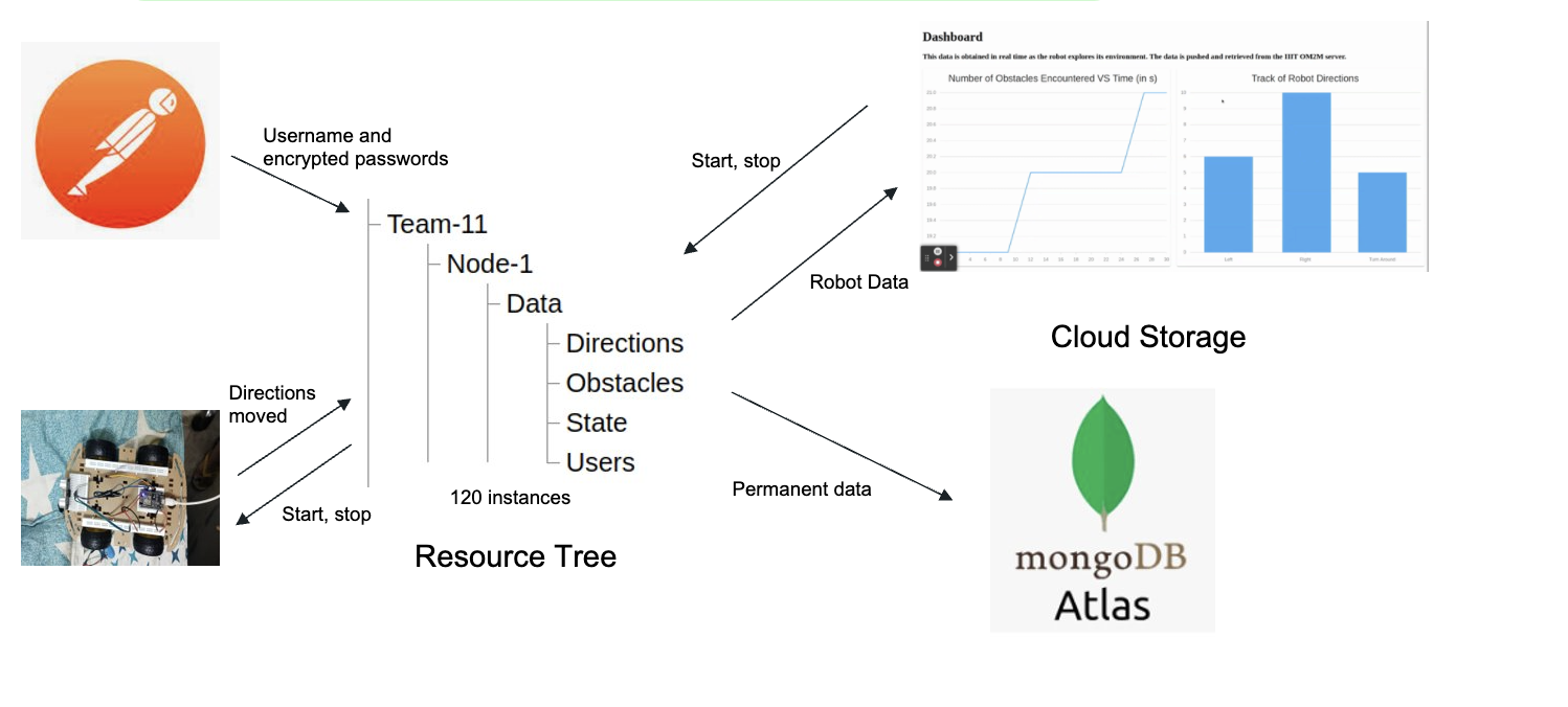
The microcontroller sends all its data to the OneM2M server for further data analysis and displaying on the dashboard. Additionally, it receives instructions to start or stop from the server and implements those instructions in the motors of the robot.
-
OneM2M and Dashboard
The OneM2M server stores information sent by the robot and shares it with the dashboard so it can be viewed by the users in the form of graphs that ensure easy ways to interpret and make inferences. Additionally, the dashboard contains start and stop buttons that send signals to the OneM2M server and consequently the microcontroller. Since the server is also connected to the MongoDB cloud database, information for permanent storage is sent to the cloud database as well.
Interactions between Microcontroller, Dashboard, OneM2M server and MongoDB Cloud Database
IoT Entity Interaction Diagram
-
System Needs
The system must always be in contact with the OneM2M server in order to upload data and for users to be able to access data on the dashboard. Additionally, it must always be connected to a MongoDB database on the cloud, as well as a 9V battery to ensure that the system can function without being connected to an external power source. The system needs connection to Wi-Fi to operate the dashboard, database and OneM2M functionalities.
-
UI Design
Since we are displaying all graphs and other data visualizations using JavaScript, the system must be able to display basic HTML, CSS and JavaScript in addition to React.js. Users can login to view the data through an interactive, easy-to-use dashboard with prompts to guide the users. Once they are logged in, they can view the simple graphs with properly labelled axes and other information.
-
Analytical System
The analytics are computed in real-time to ensure maximal relevance and usability of the data. The data is uploaded to the server, database and dashboard every 3 seconds. The graphs are uploaded dynamically as soon as they receive the data, and the graphs help users observe any trends. Since we store the long-term information about the robot's movements, users can gain even better insights about the environment being navigated by the robot.
-
Microcontroller: We used an ESP32 WROOM board with 2 motor drivers and an ultrasonic sensor attached to it. We used the pins 5,4,14,12 for output, 0 as the trigger pin and 13 as the echo pin.
-
Ultrasonic Sensor: We used the HC-SR04 sensor to measure the distance from the robot to any obstacles to ensure that the robot would be able to avoid the obstacle and move in other directions.
Quantity Value Input Voltage 5V Current Draw 20mA (Max) Digital Output 5V Digital Output 0V (Low) Working Temperature -15°C to 70°C Sensing Angle 30° Cone Angle of Effect 15° Cone Ultrasonic Frequency 40kHz Range 2cm - 400cm -
Motor Driver: We used the L298 motor driver to connect the ESP32 board with the motors and wheels of the chassis to enable movement.
Quantity Value Motor channels: 2 Maximum operating voltage: 46 V Peak output current per channel: 2 A Minimum logic voltage: 4.5 V Maximum logic voltage: 7 V Package: Multiwatt15
Component Circuit Diagram
- OneM2M: We used OneM2M, a communication protocol to enable communication between the server and embedded system, on the service layer. We sent data from the robot car to this server using POST requests. These functions are hi-lighted in the oneM2M_functions.py file.
- MongoDB: We used MongoDB Atlas, a cloud database that allows users to store information in the form of collections and documents in a NoSQL format. We share the server data with the cloud database using GET and POST requests. The functions used have been detailed in the OM2M_to_Atlas.py file.
- Sensor: The HC-SR04 sensor uses the echo pin and trigger pin to receive input about the distance from the closest obstacle. It sends out a pulse at regular intervals and measures the distance based on the time taken to get a response. The functions used for this have been detailed in the ultrasound.py file. It uses I2C protocol to communicate with the microcontroller, an asynchronous communication protocol that works extremely well over short distances.
- Dashboard: The dashboard is built using HTML, CSS and JavaScript (primarily React.js) and it fetches the data from the MongoDB server and from the OneM2M server. We used GET requests to obtain the data and present it in visually appealing formats for users.
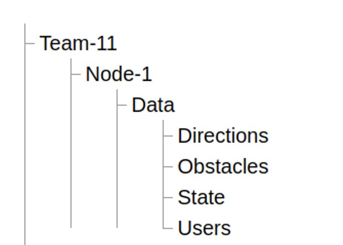
OM2M Resource Tree
-
Login: Systems must be connected to the internet, and the OneM2M server, and support HTML, CSS, JavaScript and React.js.
-
Data Visualization: The system must support React.js and a few JavaScript libraries to visualize the data.
Login Screen
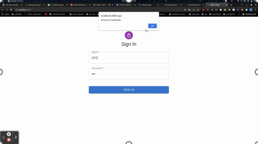
Login Failed Screen
Dashboard Screen
All the data collected upon hitting an obstacle is sent along with a timestamp to the server, where it is stored in a resource tree with containers for the directions, obstacles, users and state (start or stop). The data is then sent to the web based dashboard and to the MongoDB database as well. All the data is encrypted and private to ensure maximum security. To conserve the limit of 120 instances, we push data to the cloud when the threshold is reached, and empty the container. We display graphs showing the frequency of the obstacles with respect to time, and a histogram showing the comparison of different directions chosen.
The OneM2M server and microcontrollers are the focal points of the integration of the project. The microcontroller defines the movement and connects with the sensors, and the server connects the robot to the cloud and enables sharing of the data with the dashboard and the MongoDB database.
