Adalight serial port LED driver implementation for Raspberry Pi Pico RP2040.


To ensure the LEDs will work properly with the Pico board, a 3.3V to 5V level shifter is needed. You can use an external one e.g. SN74AHCT125N or just buy a model of rp2040 that already has it built-in: Adafruit Feather RP2040 Scorpio (output: GPIO16-23), Adafruit ItsyBitsy RP2040 (output: GPIO14), Pimoroni Plasma 2040 (GPIO14-15) or Pimoroni Plasma Stick 2040 W (GPIO15).


| LED strip / Device | Single lane | Multi-segment |
|---|---|---|
| SK6812 cold white | yes | yes |
| SK6812 neutral white | yes | yes |
| WS281x | yes | yes |
| SPI (APA102, SK9812, HD107...) | yes | no* |
* you don't need parallel mode for SPI LEDs, they are already using high speed 10Mb internal data line
It's very easy and you don't need any special flasher.
-
First download the firmware directly from the Release folder.
For HyperHDR and generic rp2040 chooseHyperSerialPico_<type>.uf2firmware where type is one of supported LEDs: sk6812 cold/neutral white, variants of ws2812 and apa102.
Due to the often neglected issue of the required 5 volt logic necessary for the correct operation of the supported LEDs, we want to promote rp2040 boards with a built-in 3.3V to 5V level shifter and we provide firmware compiled to their GPIO specifications. You can find these firmware & short pin-out manuals in the archives:Adafruit_Feather_RP2040_Scorpio.zip,Adafruit_ItsyBitsy_2040.zip,Pimoroni_Plasma_2040.zip,Pimoroni_Plasma_Stick_2040_W.zip. Also you can read about their specific GPIO output in theRecommended boards with a built-in level shiftersection above.
If you are using an application other than HyperHDR, select theclassic_adalight.ziparchive, unzip it and selectclassic_adalight_HyperSerialPico_<type>.uf2firmware (note: do not use firmware from this archive for HyperHDR, they do not support my AWA protocol extension, missing many options and are simply only backwards compatible with other applications). -
Next put your Pico board into DFU mode:
- If your Pico board has only one button (
boot) then press & hold it and connect the board to the USB port. Then you can release the button. - If your Pico board has two buttons, connect it to the USB port. Then press & hold
bootandresetbuttons, then releaseresetand next releasebootbutton.
- In the system file explorer you should find new drive (e.g. called
RPI-RP2drive) exposed by the Pico board. Drag & drop (or copy) the selected firmware to this drive. The Pico will reset automaticly after the upload and after few seconds it will be ready to use by HyperHDR as a serial port device using Adalight driver.
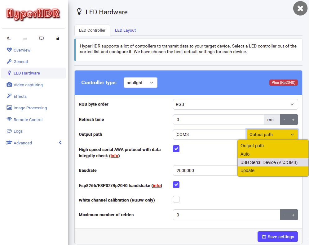
You need HyperHDR v20 or newer. Make sure you have enabled AWA protocol and Esp8266/ESP32/Rp2040 handshake options. You can leave the speed at 2000000 because the CDC driver should use the highest possible speed automatically (at least it happens on Windows).
LED output (SK6812/WS281x): GPIO2 for Data
LED output (SPI LEDs): GPIO3 for Data, GPIO2 for Clock
If multi-segment mode is enabled for SK6812/WS281x, the output for the second segment is always the next GPIO pin (OUTPUT_DATA_PIN + 1).
rp2040 allows hardware SPI on corresponding pairs of pins:
spi0 ⇒ Data/Clock: GPIO3/GPIO2, GPIO19/GPIO18, GPIO7/GPIO6
spi1 ⇒ Data/Clock: GPIO11/GPIO10, GPI15/GPIO14, GPIO27/GPI26
Pinout can be changed, but you need to make changes to CMakeList.txt (e.g. OUTPUT_DATA_PIN / OUTPUT_SPI_DATA_PIN / OUTPUT_SPI_CLOCK_PIN) and recompile the project. Also multi-segment mode can be enabled in this file: SECOND_SEGMENT_INDEX option at the beginning and optionally SECOND_SEGMENT_REVERSED. Once compiled, the results can be found in the firmware folder.
Of course, you can also build your custom firmware completely online using Github Actions. The manual can be found on wiki. Be sure to follow the steps in the correct order.
| Single LED strip | Max. refresh rate | Parallel multi-segment mode | Max. refresh rate |
|---|---|---|---|
| 300LEDs RGBW | 83 | 300LEDs RGBW SECOND_SEGMENT_INDEX=150 |
100 |
| 600LEDs RGBW | 42 | 600LEDs RGBW SECOND_SEGMENT_INDEX=300 |
83 |
| 900LEDs RGBW | 28 | 900LEDs RGBW SECOND_SEGMENT_INDEX=450 |
55 |