Aug 31st, 2024: The sander is now finished and works successfully for me. I will add more documentation in the future.
In this project I am designing and building an edge belt sander. Design constraints:
-
Using only 3D printed components + widely available off-the-shelf hardware (as far as possible) to make it fast and easy to reproduce.
-
For belt size 915 x 100 mm (but may offer other configurations in the final release).
-
Speed controllable brushless motor.
-
Belt change
and alignment adjustmentwith no tools. I had to compromise, because after adding the electronics there was not enough space for a large belt alignment screw - belt alignment now does require a hex key driver -
Low profile form factor of less than 14cm - the sander should fit into a drawer when not in use.
-
Modular design to allow for customization and faster/cheapter iteration during development.
-
Ideally: Option to power from two 18V batteries.
-
Prototype a rough full model to ensure the dimensions fit
-
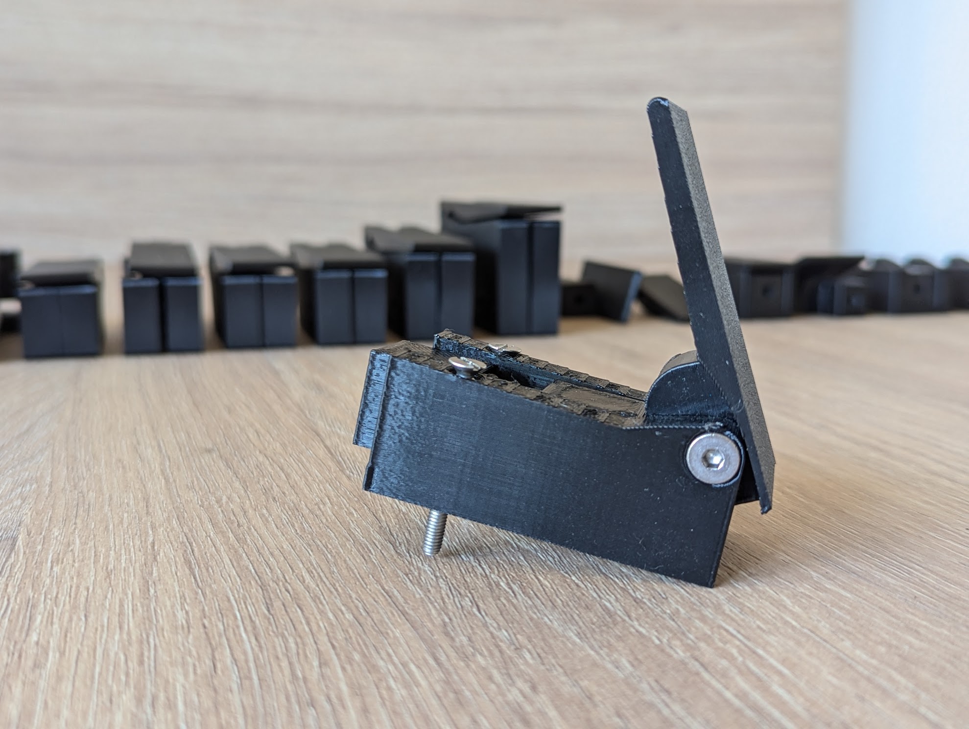
Design, test, and refine the lever mechanism for the belt tightener
-
Done after testing more than 20 different prototypes: type 1, type 2, type 3
-
Latest iteration, successfully printed and tested
-
-
Choose a motor
-
Dismissed: 997 motor, mostly due to ventilation requirements.
-
Dismissed: Skateboard motor type 1. Doesn't fit into desired envelope (see design constraints above). It is too long with the shaft included.
-
Dismissed: 6384 motor. Just about fits, but with no space left for routing the cable securely and more expensive because it requires large bearings.
-
Chosen: 90 mm skateboard motor type 2
/motor.jpg)
-
-
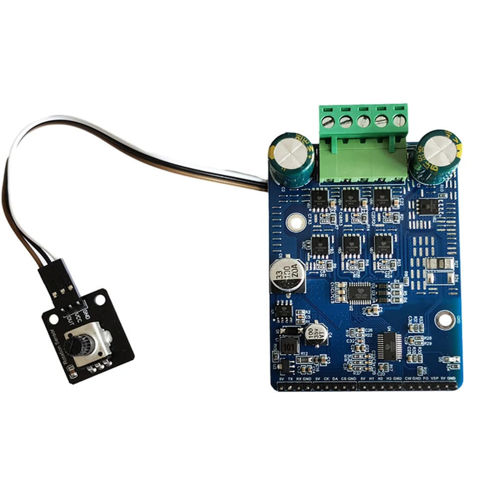
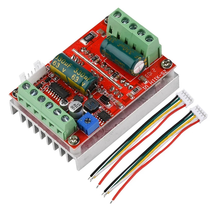
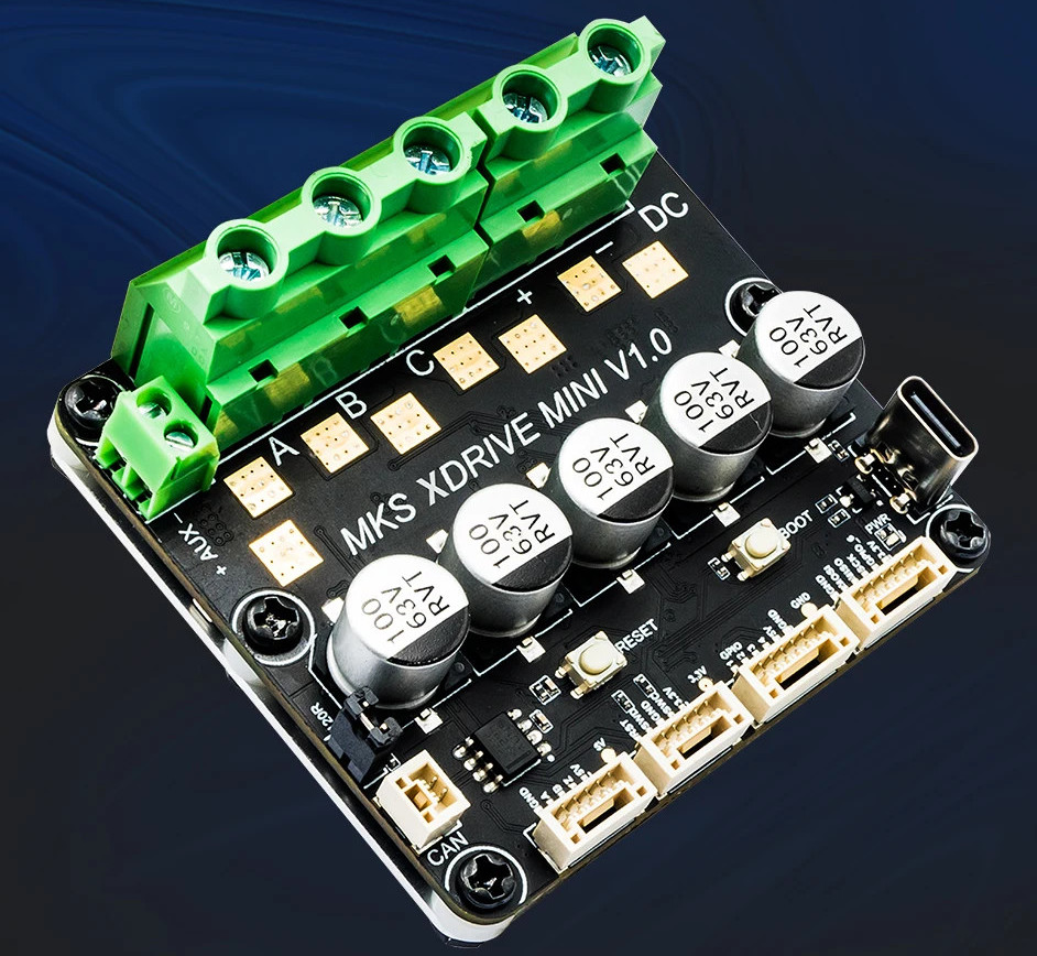
Choose a BLDC controller
-
Choose a microcontroller
- Dismissed: NodeMCU ESP8266 with 0.96 display. Large form factor made panel dimensions too large.
- Chosen ESP32 S2 Mini with separate display.
-
Create CAD models for all electronic components
-
Brake resistor (3rd party model found)
-
10k Potentiometer (3rd party model found)
-
Power switch (3rd party model found)
-
Microcontroller (3rd party model found)
-
Build and test the electronics
-
Order parts
-
Double check polarity of xdrive connectors, they use red for GND in some cases! (GPIO-connector seems wrong in photos)
The connector is indeed wrong - red is GND. Be careful.
-
Figure out maximum power draw of VCC pins of ODrive. (Sufficient for microcontroller+display? Otherwise need a separate step down module)
Should suffice: The XDrive uses an STM32F405RG, which according to its data sheet can provide a maximum of 240mA at 3.3v on Vdd. The OLED display draws 0.08W = 24.2mA, the ESP8266 has a maximum draw of 170mA and much lower with WiFi disabled. To be safe I'll keep WiFi disabled on the controller.
-
Install Logic Level Converter between ODrive and microcontroller
-
Install Hall sensor filter capacitors
-
Assemble the whole setup
-
Install and test the thermistor
-
-
Software
-
Potentiometer to set velocity
-
Resolve "ENCODER_ERROR_ILLEGAL_HALL_STATE" issue by adding filter capacitors: Encoder error ERROR_ILLEGAL_HALL_STATE
-
Figure out microcontroller / ODrive communication. Details of the investigation documented here
-
Retrieve and display actual speed from ODrive
-
Actually send the set speed to the controller.
-
-
Design and refine an electronics enclosure module to fit into the sander
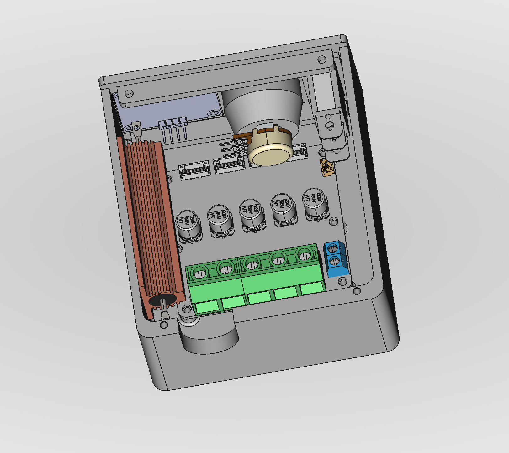
-
Potentiometer knob
-
Panel for display and speed knob.
-
Enclosure with mount plate for ODrive Mini and brake resistor.
-
Final assembly
-
-
Design and refine hub driven roller with the skateboard motor.
-
Create the new overall assembly tying everything together.
-
Fully model the design: Draft done
-
Create new belt aligner.
-
Go through every feature (screws, bearings, etc.) to try and reduce the amount of different hardware needed.
-
Check and refine all models.
-
Print, test, refine, iterate
-
-
Make a backing plate from steel or aluminium.
-
Design and build the final base plate.
-
Provide more clearance (1.5mm on each side?) between rollers and housing, to fit washers on both sides.
-
Make left carriage bearing cutouts larger - 23mm probably. It doesn't need tight clearance, as it is pulled to the right anyway.
-
Separate the carriage arm from the bracket, make them connectable using screws. For better printability/modularity.
-
Make the arm shorter, to make more space for electronics in the unit.
-
Recess the tightener knob into the unit. Knob became obsolete with new lever design
-
Bottom could be 2mm slimmer because it will be seated in a base plate anyway. Not slimmed down because space was needed for routing the cable in it.
-
Dust extraction
-
Oscillating unit
-
Reduce velocity based on proximity sensor
