This repositories purpose is to explain how the radiosonde Vaisala RS41 transmitts it's data to the ground station, how third parties can obtain the data as well as decode and interpret it.
For general information about radiosondes check out Wikipedia.
For more information about the RS41 check out my website.
Corrections and additions are always welcome, just fork the repo, edit accordingly and file a merge request.
- find out purpose of various bytes in the STATUS and MEAS Blocks
- do further subframe inverstigations
- explain how the Reed-Solomon-ECC works
- add information on xdata other than for regular ozone soundings
- obtain and analyze data from RS41-SGMs radio silence mode
- obtain and analyze data from 1.68 GHz RS41-D
My findings are really nothing new, at the end this repo is, for the most part, just an extended documentation of Zilog80s decoder, to whom most of the kudos belong.
First I will explain a little how FSK Modulation works an how we can obtain the raw bytes sent. Then I will talk about the general Frame structure. Detailed explanations on the different RS41 models can be found in the appropiate files/folders.
There is no actual decoder in this repo, just the knowledge on how to build one. However, I would like to add a simple PoC-style decoder, most likely as a C++ WPF application, at some point.
- How to obtain (G)FSK Data in general
- How to get from Audio to Data
- What did we actually obtain here?
- RS41 Frame Format
For a more detailed explanation, refer to Wikipedia.
At it's core, FSK (Frequency Shift Keying) just is binary FM-Modulation. With FM-Modulation, an analog signal (usually audio) is transmitted by varying the carriers frequency accordingly. Note that not the actual frequency of the carrier at any given moment encodes the frequency of the signal, but rather the gradual change of frequency over time. The actual frequency of the carrier is a way of transmitting the amplitude of the signal. The frequency of the signal is determined by how often the it's amplitude changes polarity, and this is why the speed at which the carrier's frequency changes represents the frequency of the signal. The actual frequency deviation of the carrier is specific for each transmission standard and has to be selected (to some degree) in accordance to the signals bandwith. This is also what differentiates Narrow-Band-FM (NFM) from Wide-Band-FM (FM) and why you have to set your receiver to NFM to be able to decode radiosondes.
So what is FSK exactly? FSK is a way of sending data, in which every symbol is transmitted by sending out a certain frequency representing that symbol. Through switching between the different frequencies (keying them) a data stream can be sent. In it's most simple form, FSK-2 (or just FSK) there are just two frequencies and thus symbols. In this case, every symbol encodes a single bit. FSK-4 uses 4 symbols, each representing two bits. Increasing the symbol count increases the channel capacity, but comes at a cost, which is not to be discussed here. The RS41 just uses regular ol' FSK, so we don't need to worry about this theoretical communication engineering stuff.
The difference between FSK and GFSK is that GFSK transitions more smoothly between the symbols, which makes the spectrum "nicer". For the purpose of this examination, we don't need to worry about this fact so much.
What happens when we decode a FSK-encoded signal with a FM demodulator (e.g. our receiver or RTL-SDR)? The FM decoder just sees the rapid change between two frequencies. During the change, there is a very high frequency, and while the symbols are sent, there is no change at all. What waveform does that remind us of - a rectangle, right! So what comes out of our receiver really is just the binary bitstream which endodes the sondes data. However, the receiver does not know anything about the symbols are defined, which means that a 1 might end up as a 0 and vice versa, meaning the signal might be inverted.
For GFSK it's really the same, just that your rectangle is looking a bit more "messed up" as it effectively was low-pass filtered for transmission.
This defines the first steps we have to perform with our audio signal.
1. Check for every sign change in the received audio file and interpret it as a byte change.
3. Check whether the signal might be inverted due to the reveiver and correct if neccessary.
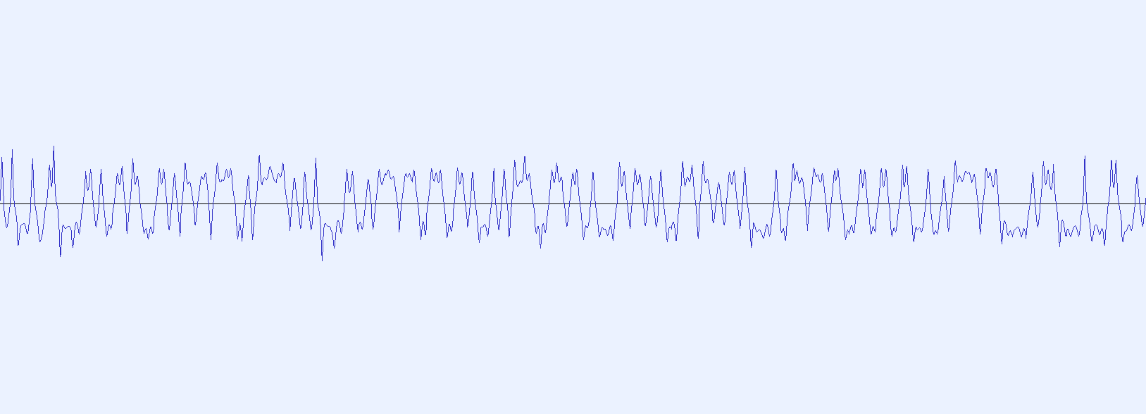
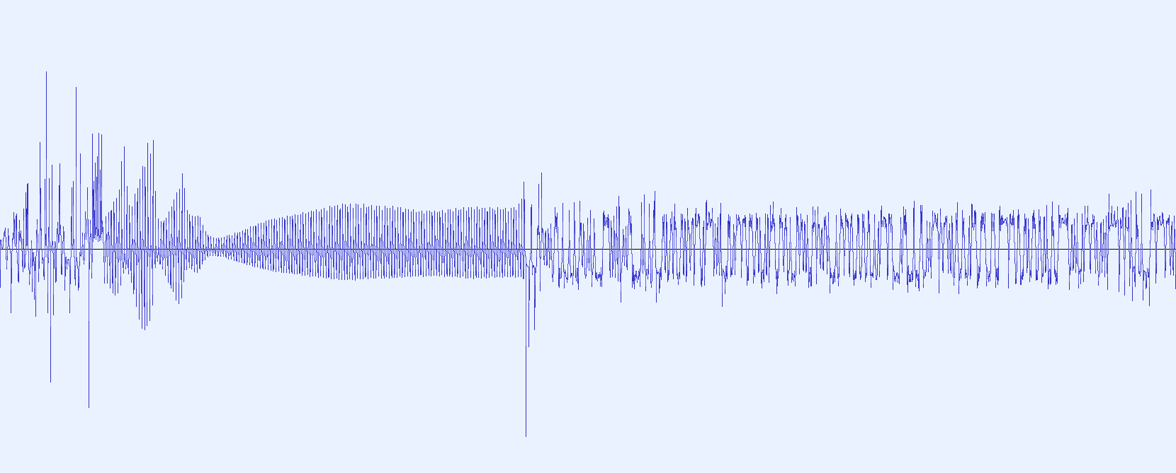
The second step above is missing, and that is for a reason. As you know, the RS41 is not transmitting continuously, there is a pause between the frames. As we can see from the datasheet, the sonde is transmitting one frame of data every second at a baud rate of 4800 symbols/second. If we take a look at an audio recording, we can identify two parts which compose a frame.
First, there is a preamble which is just a bunch of 0s and 1s alternating, which is then followed by the data. Here's an exercise for you: To which audible frequency does the preamble convert, when it is FM-demodulated and given out through a loudspeaker?
4800 Baud means there are 4800 spots for either a 1 or a 0 in the data stream. As each period of a frequency consist of both a positive and a negative half-wave this translates to an audio frequency of 2.4 kHz. We just found the characteristic "beep" in front of every frame, which makes the sonde sound so much like the first sputnik satellite, which also transmitted pressure and temperature through it's beeps.
If we interpret the preamble as binary data however, it consists of 320 bits and thus has a length of 66.7 ms. It ends with a 1. The frame which it leads is 320* bytes long and thus counts just over 533 ms.
(* unless it is an extended frame)
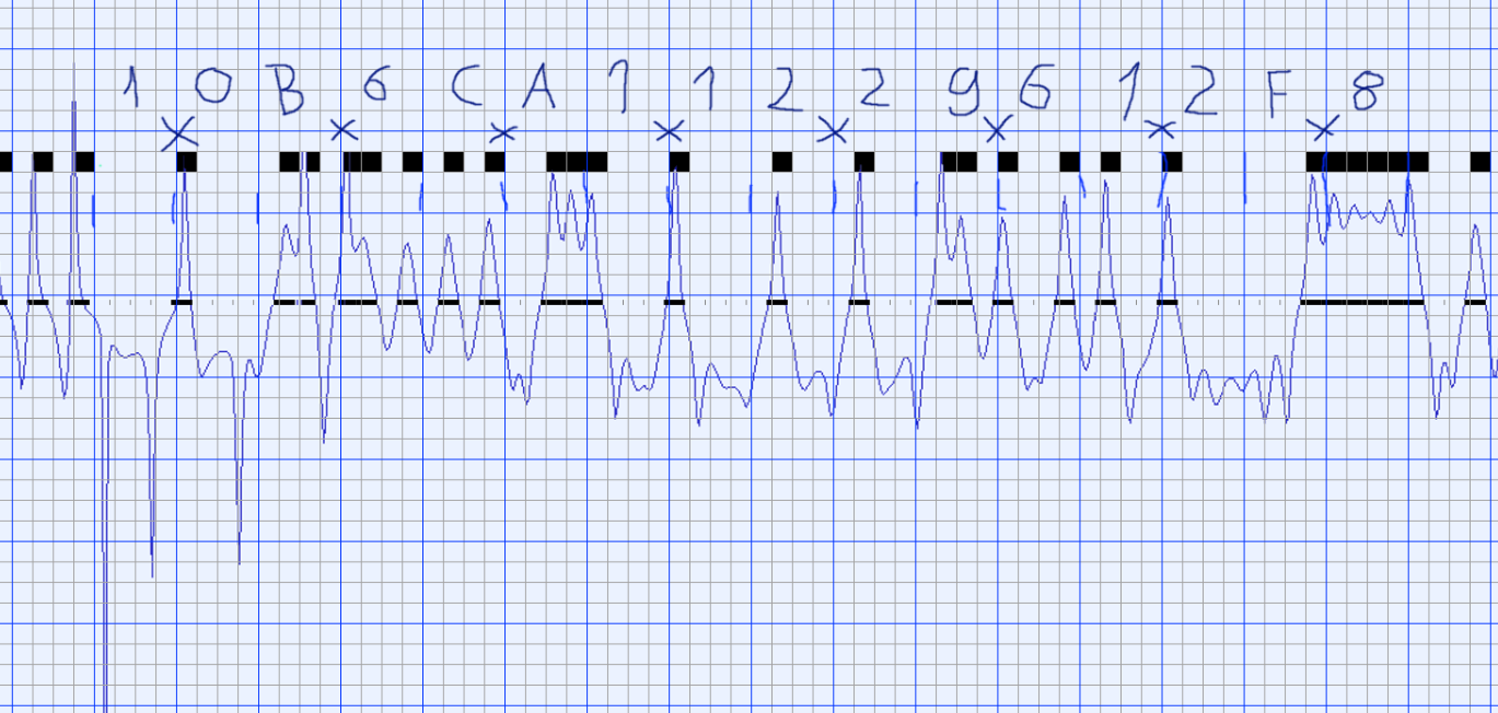
If we than take a look at the bytes that are sent after the preamble, we can find that those are the same for every sonde. This is the header consisting of 8 bytes. If you would read it as it is displayed when taking a look at the waverform, it would read as 0b0000100001101101010100111000100001000100011010010100100000011111, but how do we have to read this? This bitstream is little endian encoded, both bytewise and bitwise. That means the first nibble 0b0000 translates to 0x0, the second 0b1000 to 0x1. The first byte than reads as 0x10. The whole Header than can be decoded as 0x10B6CA11229612F8.
The sondes data is additionally xor-scrambled before sending, but not as a crude way of stopping us from decoding it, but to make sure that there always lots of 0-1 changes in the data as the the receiver has to synchronize on the transmission baud rate. This is called data whitening. The xor-value is a 64 byte long pseudorandom number generated with a known lfsr and thus can be hardcoded into the decoder. If we descramble our header from before, 0x10B6CA11229612F8, with the first 8 bytes from the mask, 0x96833E51B1490898 by bitwise xor-ing it, we get 0x8635F44093DF1A60, which we refer to as part of the raw sonde data, which is to be analyzed further.
The whole XOR-mask is as follows:
0x96, 0x83, 0x3E, 0x51, 0xB1, 0x49, 0x08, 0x98,
0x32, 0x05, 0x59, 0x0E, 0xF9, 0x44, 0xC6, 0x26,
0x21, 0x60, 0xC2, 0xEA, 0x79, 0x5D, 0x6D, 0xA1,
0x54, 0x69, 0x47, 0x0C, 0xDC, 0xE8, 0x5C, 0xF1,
0xF7, 0x76, 0x82, 0x7F, 0x07, 0x99, 0xA2, 0x2C,
0x93, 0x7C, 0x30, 0x63, 0xF5, 0x10, 0x2E, 0x61,
0xD0, 0xBC, 0xB4, 0xB6, 0x06, 0xAA, 0xF4, 0x23,
0x78, 0x6E, 0x3B, 0xAE, 0xBF, 0x7B, 0x4C, 0xC1
So here are steps two and four in our decoding chain.
2. Check for sign changes that correspond to the bitate of the sonde and find out whether the recieved data matches the known preamble or header. If that is the case, get the raw data for the rest of the frame and start processing it.
4. Transpose the bitwise little-endian to a bitwise big-endian.
5. Descramble the frame by xor-ing it with the known pseudorandom sequence.
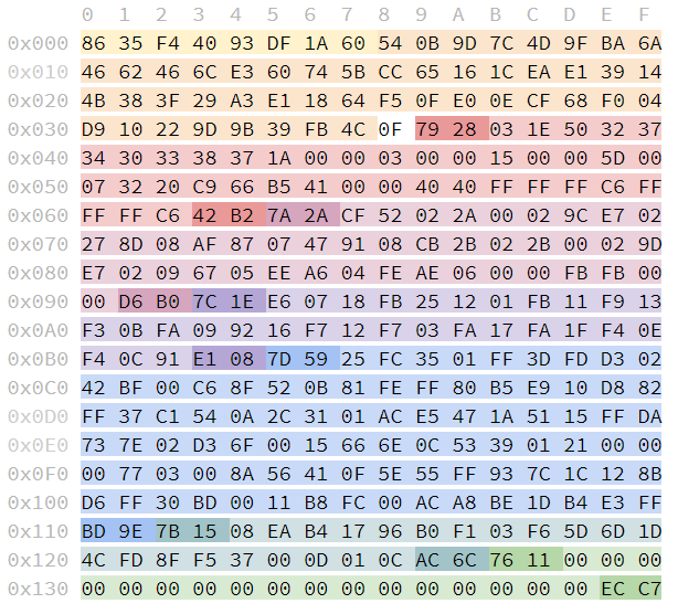
If you did all of the above, you will end up with a frame which will look somewhat like this (except you had a sonde which transmitts an exteded frame, for example an ozone sonde)
The general structure of each frame is as follows.
Bytes [0x000-0x007] contain 8 bytes header, which is always the same.
After that follow 48 bytes of reed-solomon error correction data at [0x008-0x037], which can be used to identify and correct transmission errors.
Byte [0x038] encodes the frame type and is 0x0F for a regular, and 0xF0 for an extended frame.
And after this there is a varying number of blocks, which share a common structure. A block consist of 2 bytes head, its data, and two byters tail. The first byte of the head is the block id which is unique for each type of block. The second byte is the length of the block, without head and tail. The tail finally is the CRC-16 over the data part of the block.
Now, please go to the right file/folder for your type of sonde and continue reading there. You should also keep in mind that the data is still bytewise little-endian encoded.


