This repository contains all hardware documentation for my delivery robot project - ROVER6. It is not complete yet as I gradually add documentation here.
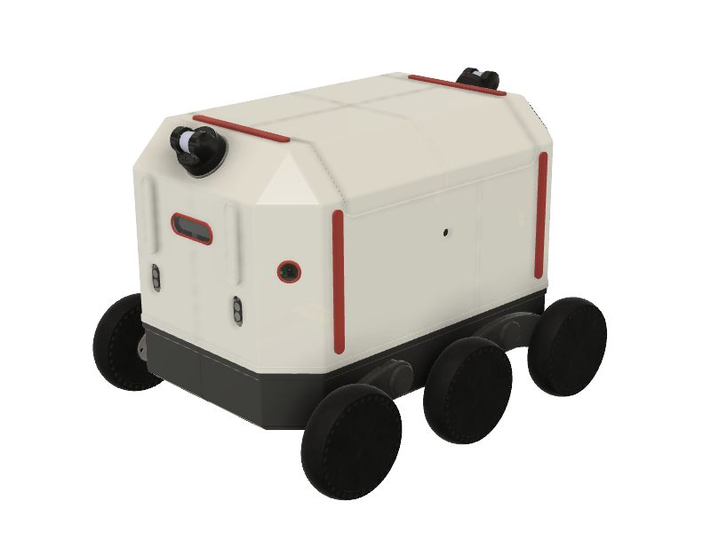
ROVER6 is a 6WD DIY delivery robot controlled with ROS. It is a hobby research robotic platform for building your own sidewalk delivery robot. Several principles were used when designing it:
- Flexibility. You can change configuration of the platform by redesigning or just removing components for your particular purpuse.
- Repeatability. ROVER6 is designed to use commonly available production technologies, like sheet metal cutting and bending, 3D printing. Electronic boards and components are mostly generally available in online stores but for several custom boards. But even those boards can be replaced with a set of generally available ones.
- Wide range of technology to study. Building ROVER6 involves understanding of different mechanical production approaches, electronics, robotics, software and many more.
The project goal is to create a repeatable sidewalk delivery robot platform which can be teleoperated or operate autonomously in a simplified environment.
You can find videos describing the project progress on my Youtube channel.
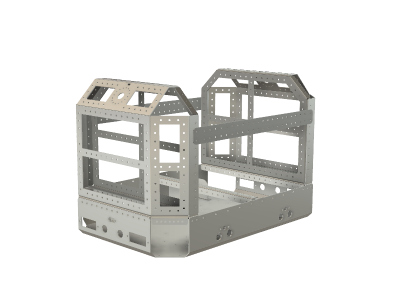
ROVER6 is built around a main frame which is created using laser cutting and bending 2mm sheet stainless steel. The frame is designed in a way to carry different components and supports changing them by providing a grid of mounting holes, so potentially any CPUs, sensors or whatever you need can be placed on the robot.
You will find 3 files for every part of the frame in the frame subfolder - a STEP 3D model, a DXF file for cutting and a PDF file with bending angles specification. There is also an assembly STEP file which contains all parts of the frame assembled.
TODO
TODO
As a complicated electromechanical system ROVER6 operaconsists of quite a bunch of electronic stuff. Most of the components are off the shelf ones.
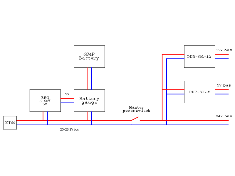
The power network inside ROVER6 consists of 3 power buses. The main bus is directly powered from battery, operates near 24V and is used to supply power to motors, some other 24V loads, like lid actuators and DC-DC converters for other power buses. A 12V bus is used to supply power to Jetron Orin Nano, lidars and CAN/RS485 interface. A 5V bus is used to supply power to Jetson Nano, Keenetic router, USB hub, ultrasonic sensors, LED strips and other 5V loads.
ROVER6 power source is a 6S4P Li-Ion battery produced by a local E-Bike shop - E4BIKE. This battery operates in 20-25.2 V range and have a built in BMS.
Mateksys dronecan digital power monitor board is used as a battery fuel gauge to monitor battery state and charge/discharge processes. To monitor battery voltage correctly it is powered through a dedicted Mateksys micro BEC 6-60V to 5V board.
Meanwell DDR-60L-12 is used to provide power to 12V bus.
Meanwell DDR-30L-5 is used to provide power to 5V bus.
An XT-60 connector on the rear side of ROVER6 is used for charging.
The main compute power is provided by NVidia Jetson Orin Nano board. This board runs ROS master and most of robot nodes. Perception devices, like lidars and realsense cameras are connected to this board. Additional compute power is provided by old good NVidia Jetson Nano. This board is used to connect supplemental cameras and to run remote control nodes.
There are several communication systems inside ROVER6.
The gigabit ethernet LAN is provided by a switch which is buit in the Keenetic router. It is used to connect compute nodes and CAN/RS485 gateway together and, through an LTE modem built in the router it provides Internet connectivity to the router. A Keenetic Hero 4G+ is used as the router/switch in ROVER6.
ROVER6 has 3 industrial buses inside to connect different sensors and devices to ROS - 2 CAN buses and 1 RS485 bus connect to Waveshare 2 channel CAN and RS485 gateway.
The first CAN bus is used to monitor and control ODdrive boards which operate motor wheels.
The second CAN bus is used for Dronecan to communicate with battery gauge and ROVER6 lid & lights controller and potentially can be used to connect any other Dronecan compatible devices.
RS485 bus runs modbus protocol to communicate with ultrasonic distance sensors and potentially can be used to connect any other modbus devices.
TODO: communication schematics
ROVER6 perception perepheral includes 3 different types of sensors.
Lidars - there are 2 Unitree 4D LiDAR L1 lidars on the robot, one on the front and one on the rear side of the robot. Lidars are mounted with 45 degree inclination. As this particular lidars have 360x180 degree field of view at this position they are able to fully cover all objects around the robot and also cover the road in the front and behind of the robot.
Cameras - there are 2 Intel RealSense D435 depth cameras on the robot, on on the front and one on the rear side of the robot. This cameras are used for visual perception as well as main front and rear camers for teleoperation. There are 2 additional Arducam USB cameras on the front left and front right sides of the robot. Those cameras are used to extend field of view for teleoperation. Additional Arducam USB camera with a wide angle lens is installed inside the robot lid to monitor the load/unload process.
Ultrasonic distance sensors provide additional level of safety - 2 sensors are installed on the front and 2 sensors are installed on the rear sides of the robot. Waterproof ultrasonic sensors with RS485 interface are used.
TODO
TODO
TODO
This project is distributed under Creative Commons CC BY-SA license


