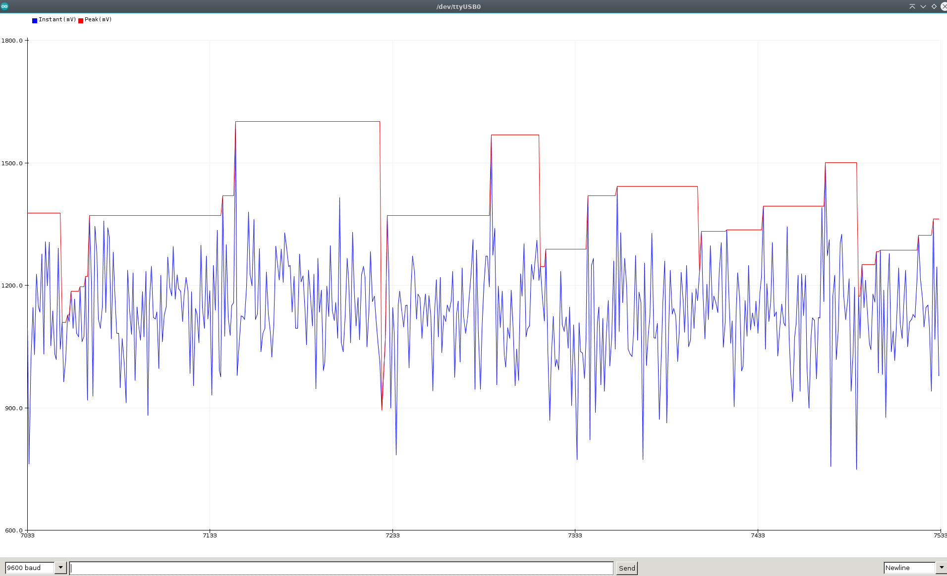
The Arduino library SensorWLED splits the input from a varying analog signal from the ADC into components, i.e., provides the capability of a sample-and-hold circuit. The library has methods that return ADC input as read (instant), while other functions hold the peak sampled value while decaying with user-set decay parameters.
- Create microphone input VU-meters.
- Trigger a high-value event action with, for example, a microphone.
- Observe disturbances/noise/spikes on a steady DC level which occur widely apart in time.
- Keep peak value, i.e., the sample reading on display, long enough for humans to notice the value.
- Use it for a voltage display with built-in calibration routines for improved accuracy.
- Scale up the attenuated resistor network input voltage to match the displayed voltage.
- Measure WLED peak electrical current with a sensor like the WLED DC Sensor Board.
The library was designed explicitly with the last point in mind, i.e., for measuring fast-changing Neopixel pixel currents. Unfortunately, the varying current level is often only roughly estimated when creating WLED-based projects.
In the Arduino IDE, scroll down the long list below File->Examples and find SensorWLED. Many examples use the Arduino library Rdebug for convenience but are not strictly part of the library itself. However, the Arduino EEPROM library is required.
#include <SensorWLED.h>

// Instantiate a SensorWLED object with the ESP32 ADC input pin.
SensorWLED ProbeOne(33);       // Use pin 0 for ESP8266
DynamicDataType_t ParamsOne;   // User parameter structure

double mv_value ;             // Instant ADC value
double mv_pk_value ;          // Peak ADC value
Define in the setup() section the required library parameters and call the begin-method, for example:
void setup() {
    Serial.begin(9600);
    delay(250);

    ParamsOne = {
        .bits_resolution_adc = bits12,      // Use 'bits10' for an ESP8266
        .mv_maxvoltage_adc = mv_vcc_3v3,
        .ms_poll_time = 250,
        .ms_hold_time = 1000,
        .decay_model = exponential_decay,
        .decay_rate = 1,
    };

    ProbeOne.begin(ParamsOne);  // Sets all parameters
}
In the loop() function, the two primary methods are to retrieve the peak sample and instant ADC values.
void loop() {

    // True at set 'ms_poll_time'
    if (ProbeOne.updateAnalogRead() == true) {
        mv_value = (double) ProbeOne.getMappedValue();
        mv_pk_value = (double) ProbeOne.getMappedPeakValue();
        Serial.print(mv_value);
        Serial.print(",");
        Serial.print(mv_pk_value);
        Serial.println();
    }

    /* Do other tasks */
}These three parameters affect the hold function behavior. If the ADC input is a step function from a HIGH to a LOW level and stays LOW, you may see an actual decaying signal. Every time the instant input ADC value is higher than the previous value, the sampled peak value will track that until it is lower again.
The hold-time is only applied on a decreasing voltage, as shown above.
The value set with decay_rate is a multiplication factor to the instant value. With the decay_model linear_decay, the decay_rate value has to be less than one. With the decay_model exponential_decay, the used factor is exp(-decay_rate). The choice of model depends on how the sample value should decrease at the set hold_time event. The two timers are evaluated only in the updateAnalogRead method.
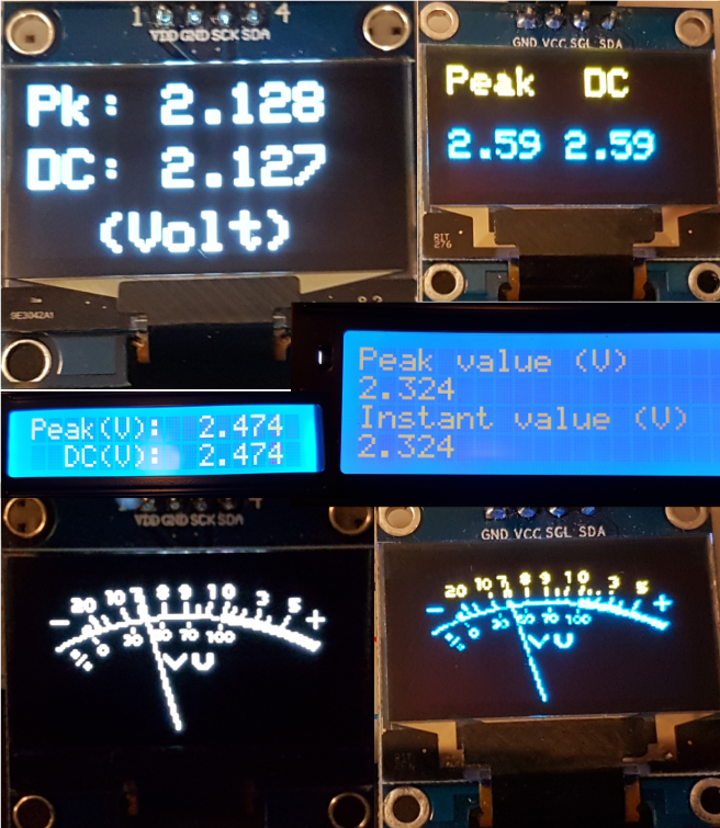
The examples sketches with 0.96" OLED 128x64 SSD1306, 1.3" OLED 128x64 SH1106G, and 2x16 or 4x20 LCD I2C displays
Instantiating parameters can be used to improve accuracy.
 // Constructor, default: no calibration or averaging smoothing samples applied
    SensorWLED(uint16_t analog_pin, float mv_offset = 0.0, float slope = 1.0,
                                                        uint16_t samples = 0 );
The mv_offset sets the zero offset if the ADC reading does not show zero voltage with the input tied to GND.
The slope adjusts the reading when calibrated with a reference voltage. Reduce the ADC voltage to increase the input range, and adjust the readout with the slope parameter.
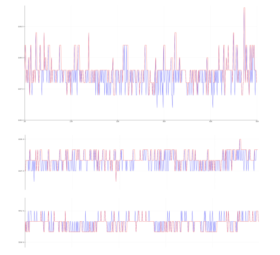
Finally, reduce the volatility of readings by increasing the number of samples. The calling function returns the calculated average.
The effect of ADC values with 'samples' set equal to zero (i.e., no sampling), five and ten averaging samples.
// SensorWLED.h
#if !defined(US_ADC_CONVERSION_TIME)
    #define US_ADC_CONVERSION_TIME 250		// microseconds
#endif
Smooth the ADC readings in the preset time window for the period samples x US_ADC_CONVERSION_TIME. The time between each new sample in the averaging calculation is very conservative to ensure that the microcontroller has enough time to complete each ADC conversion cycle. Redefine if required in the sketch.
The library requires the Arduino standard EEPROM library. The begin method saves all parameters to the flash-emulated EEPROM on the ESP32/ESP8266.
In addition, the built-in CRC32 checksums test to ensure no unnecessary write operations.
- Each ADC-channel instance has its dedicated memory area to save its configuration data.
In addition, there are auxiliary methods to read/write/calculate crc32, etc.
Currently, there is no simple way to change the running parameters dynamically. However, a future enhancement objective is to implement this functionality.
Click on the green Library Manager badge above for instructions,
or use the alternative manual installation procedure.
- Navigate to the Releases page.
- Download the latest ZIP archive in
~/Arduino/libraries. - Unzip the archive.
- Rename the new directory. Remove version-code or master in the name like this for
SensorWLED. - Restart Arduino IDE.
- In Arduino IDE, scroll down the long list below
Sketch->Include Libraryand findSensorWLED.
The 10A current shunt board, i.e., Sensor WLED board, is soon to be released.
You can purchase all the latest designed boards on Tindie. We appreciate your support.
[1] Aircookie's WLED.
[2] atuline's Sound Reactive WLED.


