IBM Cloud™ comprises over 60 data centers around the world. Additionally, IBM Cloud includes 6 multi-zone regions (MZR) where at least 3 geographically dispersed and independent data-centers can be clustered together over a very high-speed, low-latency network to provides the infrastructure for highly available applications. Within these MZRs, you can create your own Virtual Private Cloud (VPC), which provides a software define network within the IBM public cloud. VPC gives you the security of a private cloud with the agility and ease of use as a public cloud.
This tutorial will walk thru creating a custom Virtual Private Cloud (VPC) within an MZR of the IBM Public Cloud. We will cover the following topics:
- Create a custom Gen2 VPC from scratch using the IBM Cloud UI.
- Creating custom subnets with BYOIP (Bring your own IP).
- Creating custom x86 and Power9 Virtual Server Instances (VSI) within this VPC.
- Creating a 3-node active-active clustered MariaDB database with Galera.
- Creating a 3-node active-active clustered Wordpress application using GlusterFS.
- Verifying high availability and scalability of the VSIs within the MZR.
The following diagram depicts the topology of what you will build in this tutorial. You'll note the topology includes multiple zones which include multiple subnets, which are isolated by zones and logical tiering with security groups to protect what traffic is allowed into and out of the VSIs within these subnets. While this tutorial focuses on a single MZR, which provides a great deal of resilency from any single point of failure (SPOF), it does not address a complete city outage such as a natural disaster. For Disaster Recovery scenarios, it is recommended to deploy your application across two or more MZRs as described in this article.

- 3X redundancy is needed to achieve 99.999% availability (i.e. <5m per year).
- IBM zones within an MZR are isolated from other zones and provide complete redundancy from other zones within an MZR (i.e. there is no single-point-of-failure across zones).
- 3 nodes is often recommended for many clustering services (e.g. MariaDB Galera, VMWare, Kubernetes, etc.).
IBM Cloud™ Virtual Private Cloud (VPC) is a virtual network within your Cloud account. It provides fine-grained security, multi-tenant isolation, and network traffic segmentation. Each VPC is deployed to a single region; however, a VPC can span multiple zones (i.e. Data-centers). For example, in an MZR with 3 data-centers, your VPC can span all 3 data-centers providing a logical network that sits on top of multiple physical networks across these data-centers. This allows you to recreate your own premise network (e.g. 10.10.x.x or 192.168.x.x) without conflicting with other tenants that use these same IP addresses within their custom VPC. This makes migrating to IBM Cloud easier and reduces risk associated with changing your application's underlying network.
The IBM Cloud is constantly adding new features and services, which is why you will see multiple Virtual Server Instance (VSI) options:
- Classic VSIs where you'll find VLAN segregated servers, bare metal servers, VMWare servers, SAP servers, etc.
- Generation 1 VPC VSIs
- Generation 2 VPC VSIs
This tutorial will use Gen2 VPC VSIs.
-
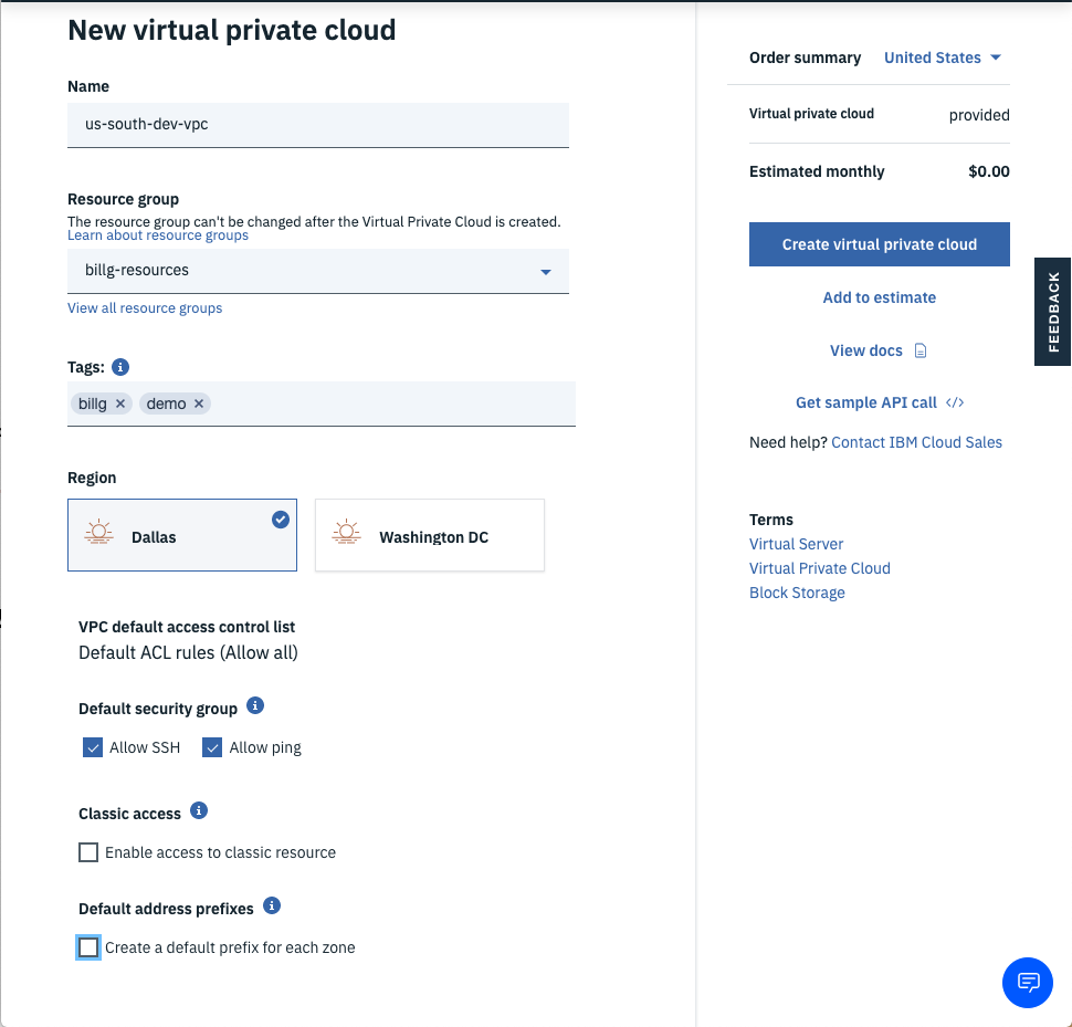
Login to the IBM Cloud and click the hamburger stack, then select VPC Infrastructure (VPC) followed by Create VPC for Gen 2.
-
Fill in values for the New virtual private cloud wizard:
-
Enter a name for your new VPC (e.g.
us-south-dev-vpc). -
Choose a Resource group. Learn more here.
-
Add tags to organize your team, project, function, etc. Learn more here.
-
Select the region for the VPC. VPCs are tied to regions.
-
Leave Allow SSH and Allow ping for now -- you can remove these rules once you get connectivity working.
-
Uncheck Create a default prefix for each zone since you will create your own subnet.
-
Click the Create virtual private cloud button.
-

The VPC defaults are designed for simplicity in getting started and may require modification for a production environment where security is paramount.
- Drill into your newly created VPC.
- Click the Default ACL link if you wish to change the name to something more descriptive (e.g.
default-nacl). - Click the Default Security Group link to change the name (e.g.
web-security-group).
- Click the Default ACL link if you wish to change the name to something more descriptive (e.g.
- Click the Manage address prefixes link followed by the New prefix link.
- Add IP range CIDR block addresses per the Architecture diagram.
- Note: Using a subnet naming convention makes it easier to remember the IP addresses. For example, using 10.10.10.0 for Dallas1 and then 10.10.20.0 for Dallas2. Use what works for you, but consistency and a standard makes it easier with communicating to the team.
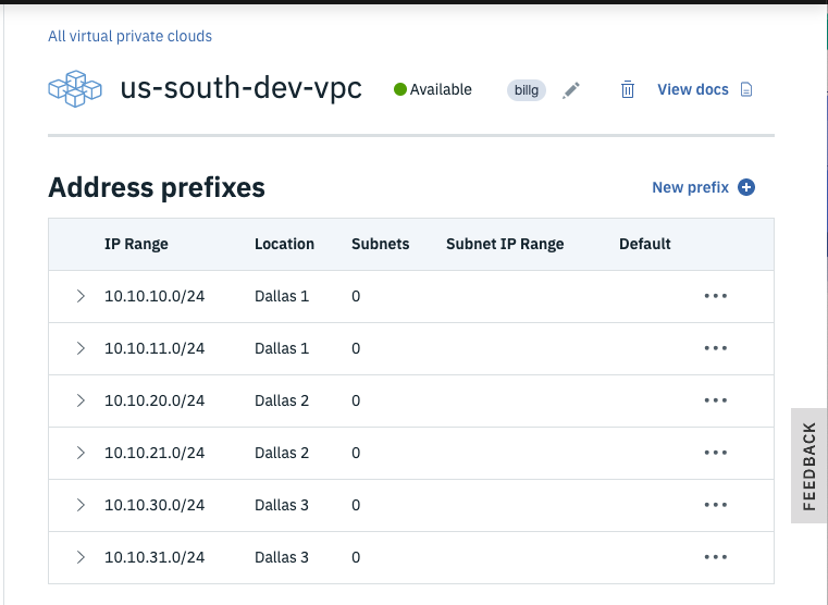
- Note: Using a subnet naming convention makes it easier to remember the IP addresses. For example, using 10.10.10.0 for Dallas1 and then 10.10.20.0 for Dallas2. Use what works for you, but consistency and a standard makes it easier with communicating to the team.
- Click the Overview breadcrumb link to return to the main VPC page.

Isolating VSIs to separate subnets allows easier firewalling and protection (e.g. only allow DB connections to the DB subnet and only from the web-tier subnet). Also, note that subnets can't span zones.
- Click the New subnet button to launch the Subnet wizard.
- Change your data-center to match the data-center you used for your addresss prefixes. (e.g.
Dallas1) - Enter a name for the web-tier subnet such as the architecture diagram depicts. (e.g.
web1) - Add the subnet to your resource group to make management of your IBM Cloud services easier.
- Select the Address prefix that matches the Architecture diagram. (e.g.
web1uses10.10.10.0/24) - Select Attached for the Public gateway so you have outbound connectivity to the Internet (e.g. to get OS patches).
- Click the Create subnet button.
- Repeat this section for the 5 other subnets in the Architecture diagram.
- Click the VPC Layout link and select your VPC in the drop-down.
- Click each subnet box and examine the subnet names, IP address ranges, data-center location, and public Gateway IP address.
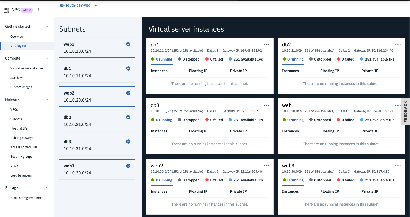
- Notice how the subnets within a zone use the same Public Gateway.

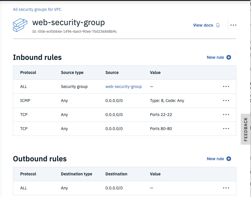
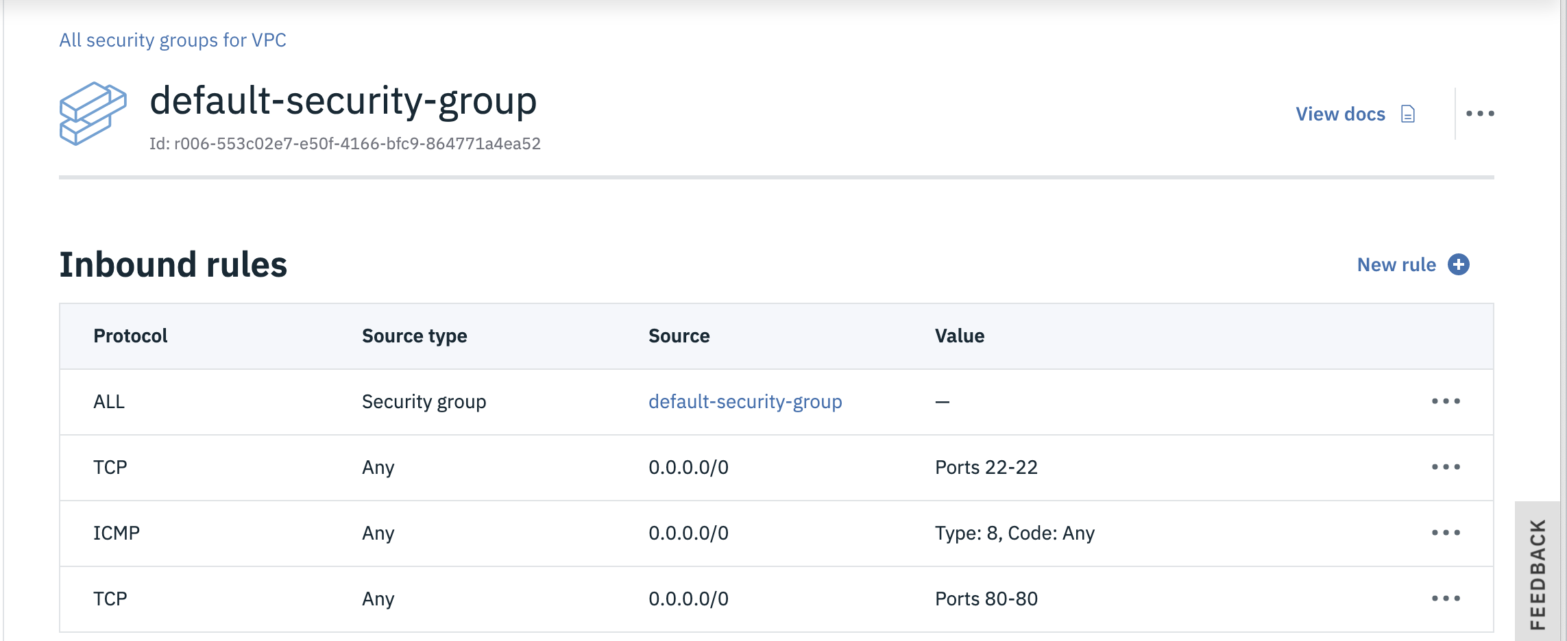
Network Interface Cards (NICs) within VSIs are attached to security groups and allow you to filter what traffic is allowed into the VSI. By default, all traffic is blocked, so you'll need to open up specific ports depending on what services within the VSI you wish to expose to other computers. A really helpful feature is the ability to allow VSIs that are attached to other security groups to connect (e.g. only allow the web-tier VSIs to connect to the db-tier VSIs.) You can read more about security groups here.
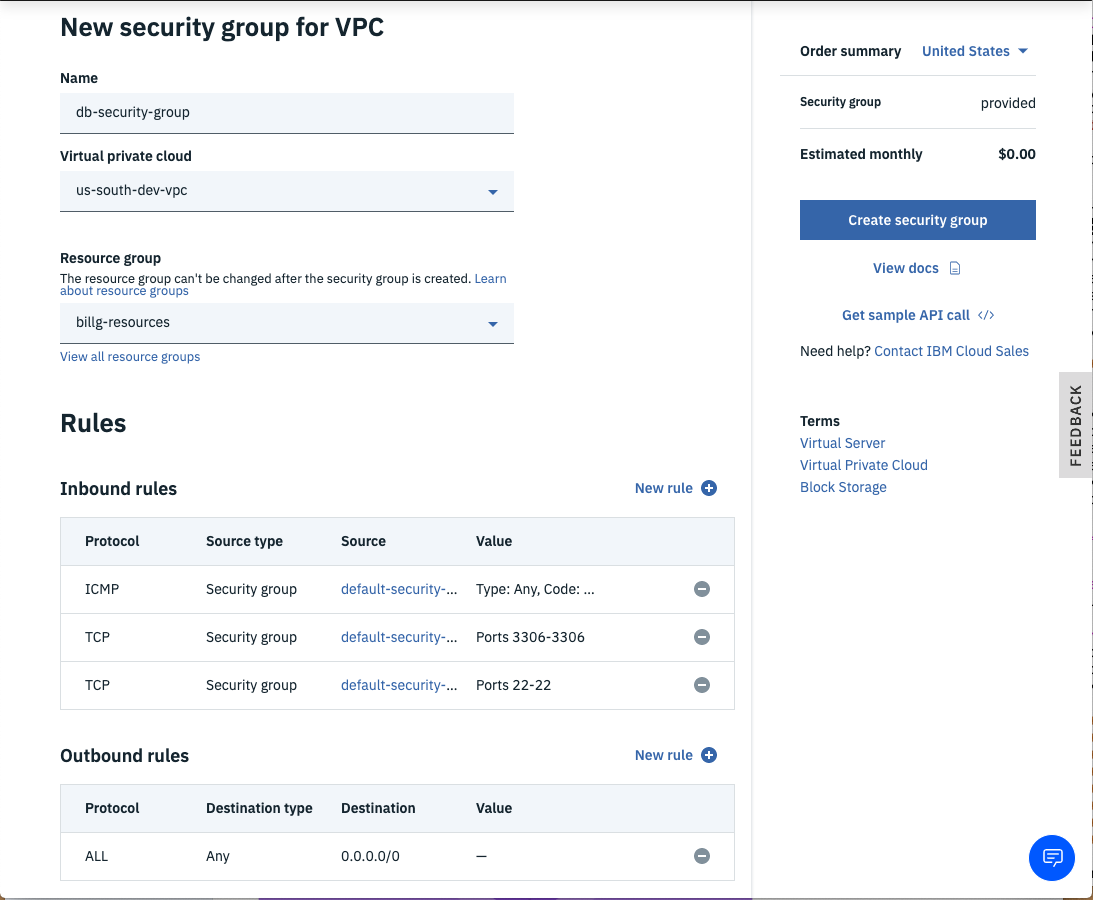
- From the left-side VPC Menu, select the Security groups menu item and click the new security group link so you can add a different security group for the database tier. You can just use the default security group for the web tier.
- Enter a name for the security group (e.g.
db-security-group). - Ensure the correct VPC is selected as well as the desired Resource group, then click the New rule link for the Inbound rules section.
- Choose TCP as the Protocol, then select the Port range radio button and enter
22for both the Port min and the Port max (port 22 is to allow SSH connections). - Next, select the Security group radio button for the Source type of the rule and choose your default security group, then click the Save button.
- Tip: this rule means that VSIs protected by this security group will allow SSH connections from other VSIs that are protected by the default security group. (i.e. only allow SSH to the DBs from the web VSIs.)
- Click the Inbound New rule link again and enter
3306(MYSQL Database port) for Port min and Port max and again select your default security group as the Source type. - Add another Inbound rule for ICMP (so you can ping the VSIs) traffic from any VSI that is attached to the default security group and click Save.
- Click the Outbound New rule link and choose All Protocols from Any Destination type to permit all outbound traffic from VSIs protected by this security group.
- Once the rules are correct, click the Create security group button.

Now that you have a VPC created, you can provision Gen2 VSIs within your custom network. These new VSIs provision rapidly (usually in seconds) and have very high-speed networking (e.g. 100Gbps). Additionally, IBM Power hardware is available in Beta, which is particularly good at multi-threaded applications as the CPU includes 2X the threads per core as x86 CPUs, making it more cost effective for multi-threaded applications like DBs, AI jobs, Apache Spark, etc. You can read more here.
-
Select the VPC layout menu item of the VPC left-side menu and choose your VPC.
-
Select each subnet of the VPC and resize the window so you can see the subnets stacked.
-
Click the ellipsis in the corner of each subnet and choose New instance.
-
Fill in the details for the New virtual server for VPC wizard.
- Enter a name (e.g.
db1). - Ensure the correct VPC is selected.
- Choose your desired resource group.
- Add any desired Tags.
- Choose the data-center that matches the diagram (e.g.
Dallas1). - For the web-tier, choose x86 as the chipset. For the data-tier, choose POWER.
- Choose Ubuntu 18.04 for the Operating System Image.
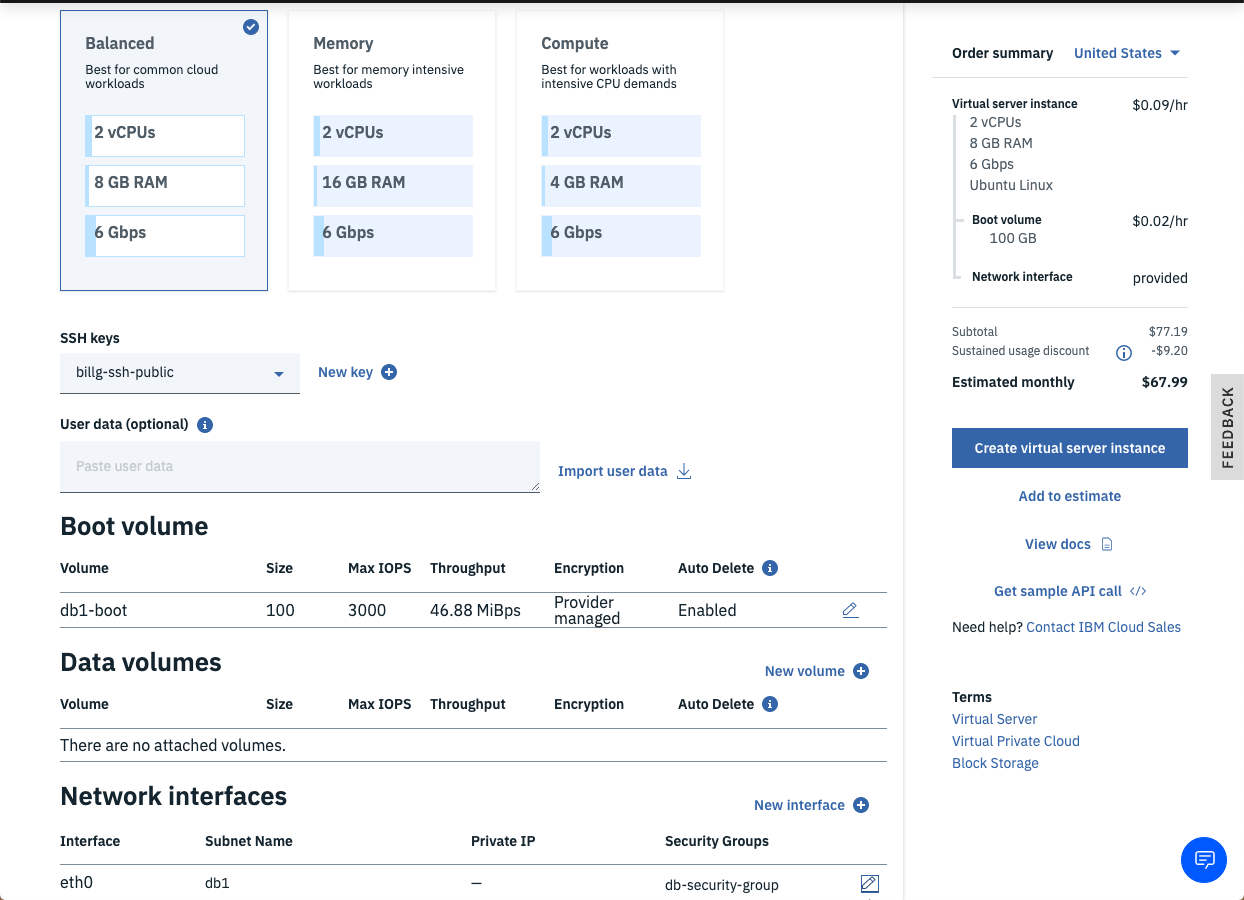
- Choose the 2 vCPUs by 8GB RAM Balanced profile.
- Click New key if your SSH key hasn't been added already; otherwise, just select your existing SSH key.
- Fill in the Add SSH Key Wizard if needed.
- Leave the Boot volume and Data volume defaults for the database VSIs, but click the pencil icon for the
eth0network interfaces and ensure the correct Subnet is selected (e.g.web1for web1 in the first data-center andweb2for web2 in the second data-center of your VPC.) - Ensure the correct Security group is checked (See the Architecture diagram if unclear.).
- Click the Create virtual server instance button.
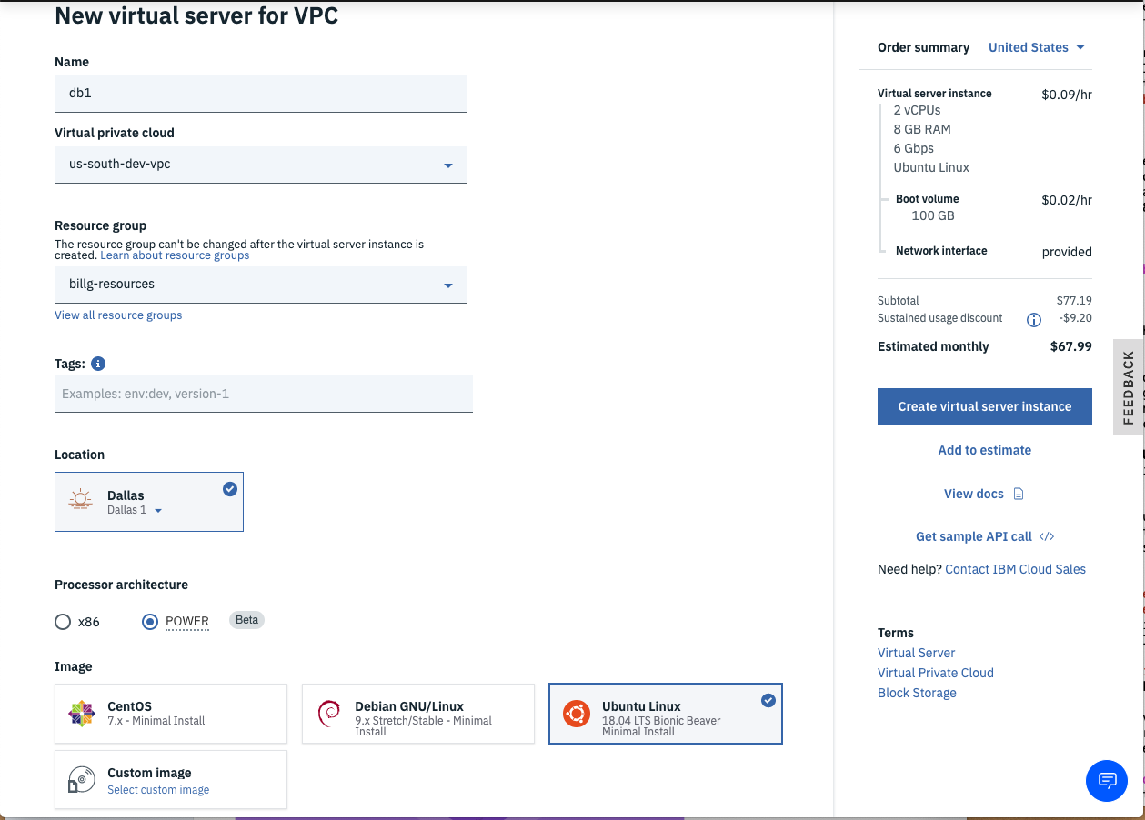
- Note: the VSI provisions very rapidly (usually in under 1 minute).
- Also note the POWER VSIs are cheaper than x86 since the HW is more performant.
- Enter a name (e.g.
-
Repeat step 4 for each VSI in the architecture diagram (i.e.
web1..web3,db1..db3).- For the
webservers, you need to add a Data volume for the Wordpress files. - Name the volume something descriptive (e.g.
web1-www-vol) using theTieredprofile. - Enter
100for the volume size (i.e. 100GB) and select the default3 IOPS/GB. - To prevent forgetting to delete this volume, click the Enabled toggle for the Auto Delete followed by the Attach button.
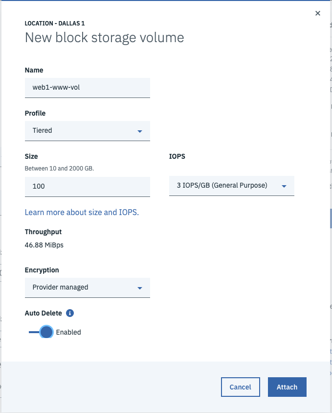
- For the
-
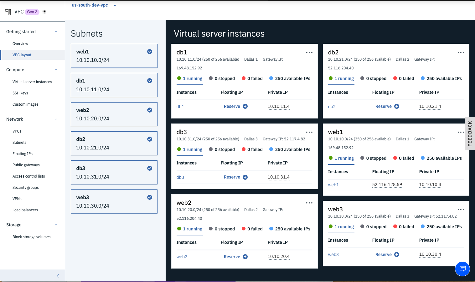
Click the VPC layout link followed by selecting each subnet to see the details of the VSIs within the appropriate subnets.
-
Click the Reserve link for a new Floating IP for the web1 instance so you can SSH into the VSI.
- TIP: VSIs don't have public IP addresses by default which is more secure; however, getting to the VSI without a public IP requires VPN or a jump server or Direct Link, etc. which is beyond the scope of this tutorial. For a production setup, the author recommends a much more hardened security architecture.
- We'll use
web1as the jumpserver to the other VSIs.


Now that you have VSIs provisioned within isolated subnets within your VPC, you will remotely login to one of your VSIs that has a floating public IP address and then test connectivity to all of the other VSIs within the VPC.
-
Copy the Floating IP from the
web1VSI that you just created and pull up a command-line terminal program (e.g. Terminal in MacOS or Putty in Windows). -
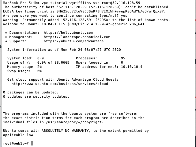
Connect to the VSI using an ssh login (e.g.
# ssh root@52.116.128.59).
-
Ping each VSI's private IP in the VPC.
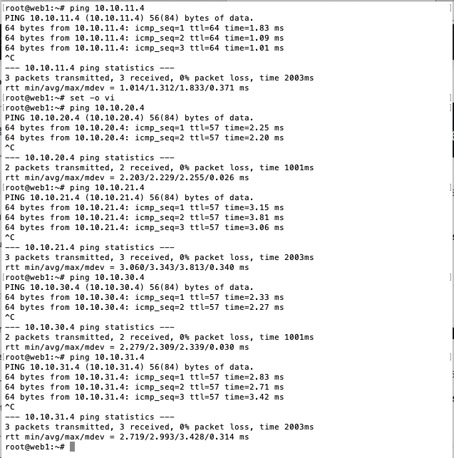
- Notice you can ping all private IP addresses (i.e.
10.10.x.4) out-of-the-box without setting up any explicit routes. IBM's VPC uses an implicit router to route traffic across your VPC.
- Notice you can ping all private IP addresses (i.e.
-
Exit out of
web1and SSH intodb1usingweb1as a jump server (e.g.ssh -J <user>@<jump-server> <user>@<target-server>) which uses your local private SSH key with the public SSH key that was added to each VSI.
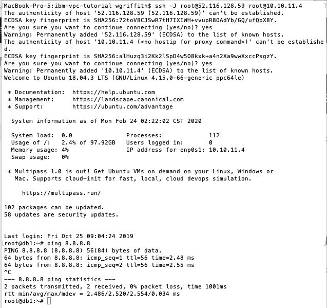
- Notice that the DB server doesn't have a public IP address, so you jumped thru the Floating IP of the
web1and then into the private IP address of the DB server.
- Notice that the DB server doesn't have a public IP address, so you jumped thru the Floating IP of the
-
Ping Google's DNS address
8.8.8.8to verify that you have outbound connectivity thru the Public Gateway that you attatched to your subnet. -
Do a
apt-get updateto verify that you can update the DB VSI. -
Run
lscputo examine the CPU details of thedb1.
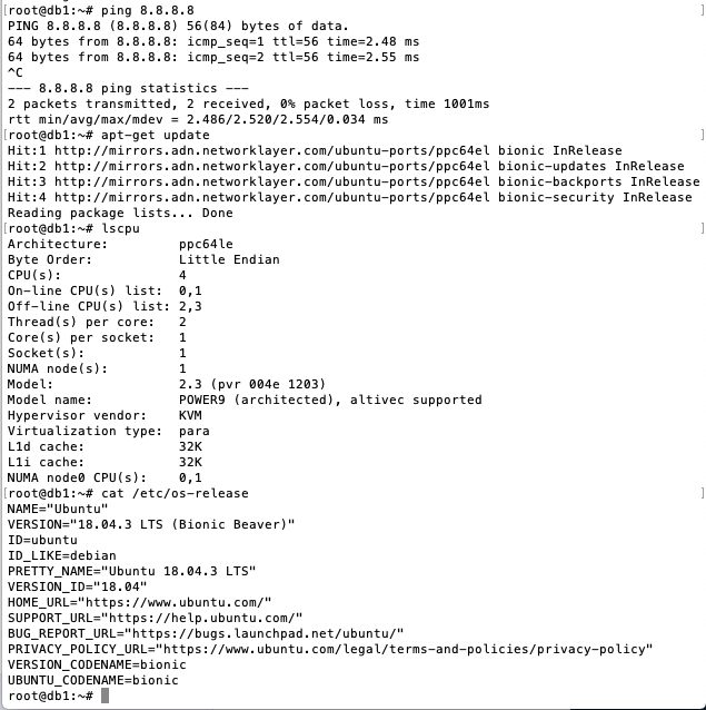
- Notice that the database server is a POWER9 CPU running the Ubuntu operating system.


In order to test the load balancer, you will install the Nginx web server on each of the web VSIs.
-
Login to the web VSI and install Nginx.
apt-get -y update apt-get -y upgrade apt-get -y install nginx systemctl enable nginx systemctl start nginx -
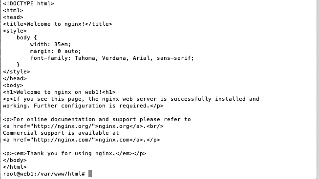
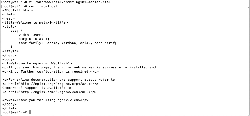
Add the VSI hostname to the default Nginx home page by editing
/var/www/html/index.nginx-debian.htmland addon <hostname>to the H1 element.
-
Test that Nginx is serving up content with
curl localhost.
-
Repeat this process for the remaining web VSIs.


The IBM Load Balancer for VPC provides the capability to route network traffic across VSIs or applications hosted within your VPC. It provides proven high availability and ensured performance. It supports Layer-4 and Layer-7 load balancing across HTTP, HTTPS, and TCP protocols. It can be configured as a public facing load balaner or a private load balancer. Many additional advanced features are supported that you can read about here.
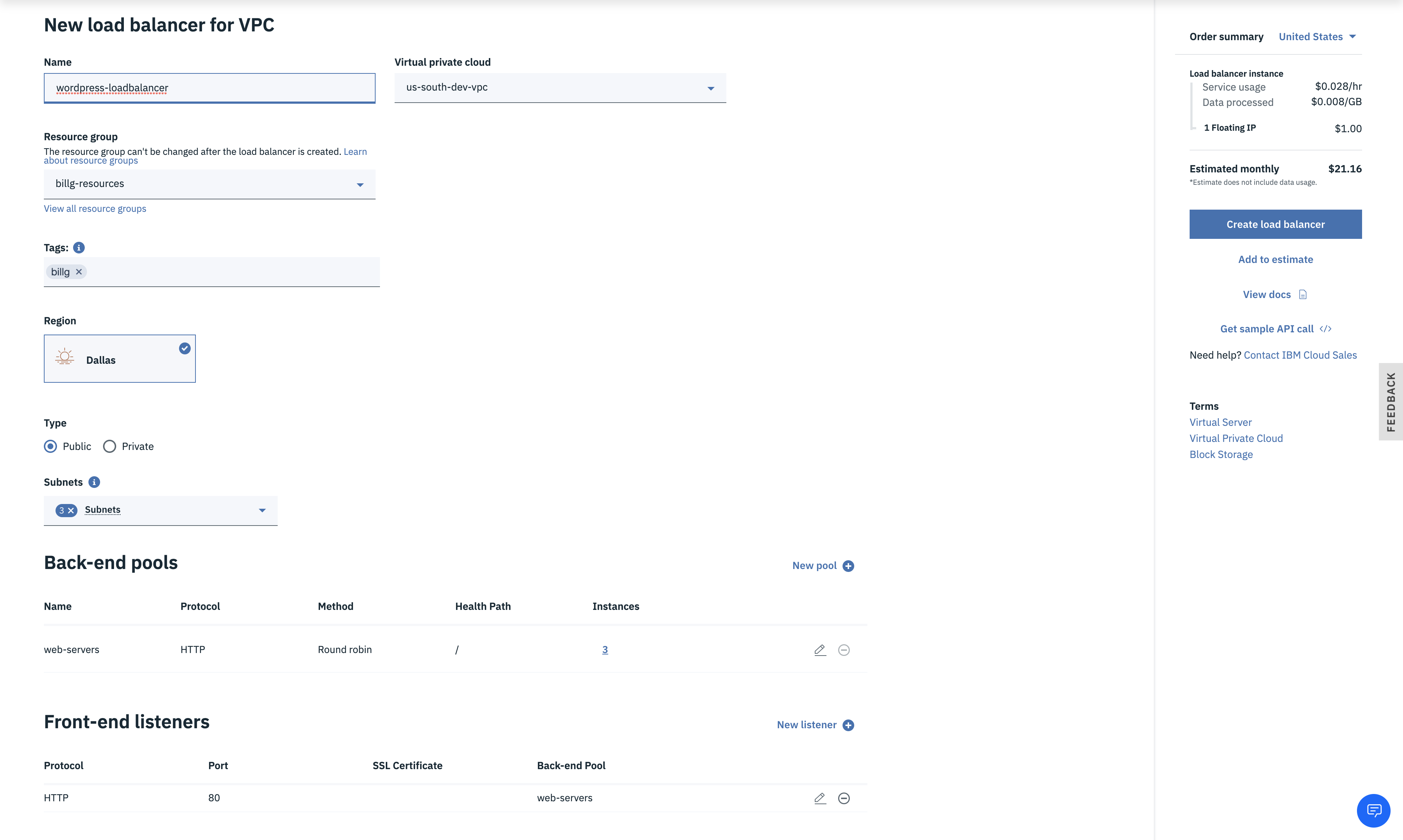
- From the VPC Infrastructure menu, click the Load balancers to add a new load balancer to your VPC.
- Click the New load balancer link within the Load balancers for VPC page.
- Enter a descriptive name for the load balancer (e.g.
wordpress-loadbalancer) and ensure the correct VPC is chosen (e.g.us-south-dev-vpc). - Select your desired Resource group.
- Add desired Tags.
- Choose the Region where you VPC resides.
- Choose Public as the type of load balancer.
- Click the Subnets drop-down and choose the 3
websubnets you previously created.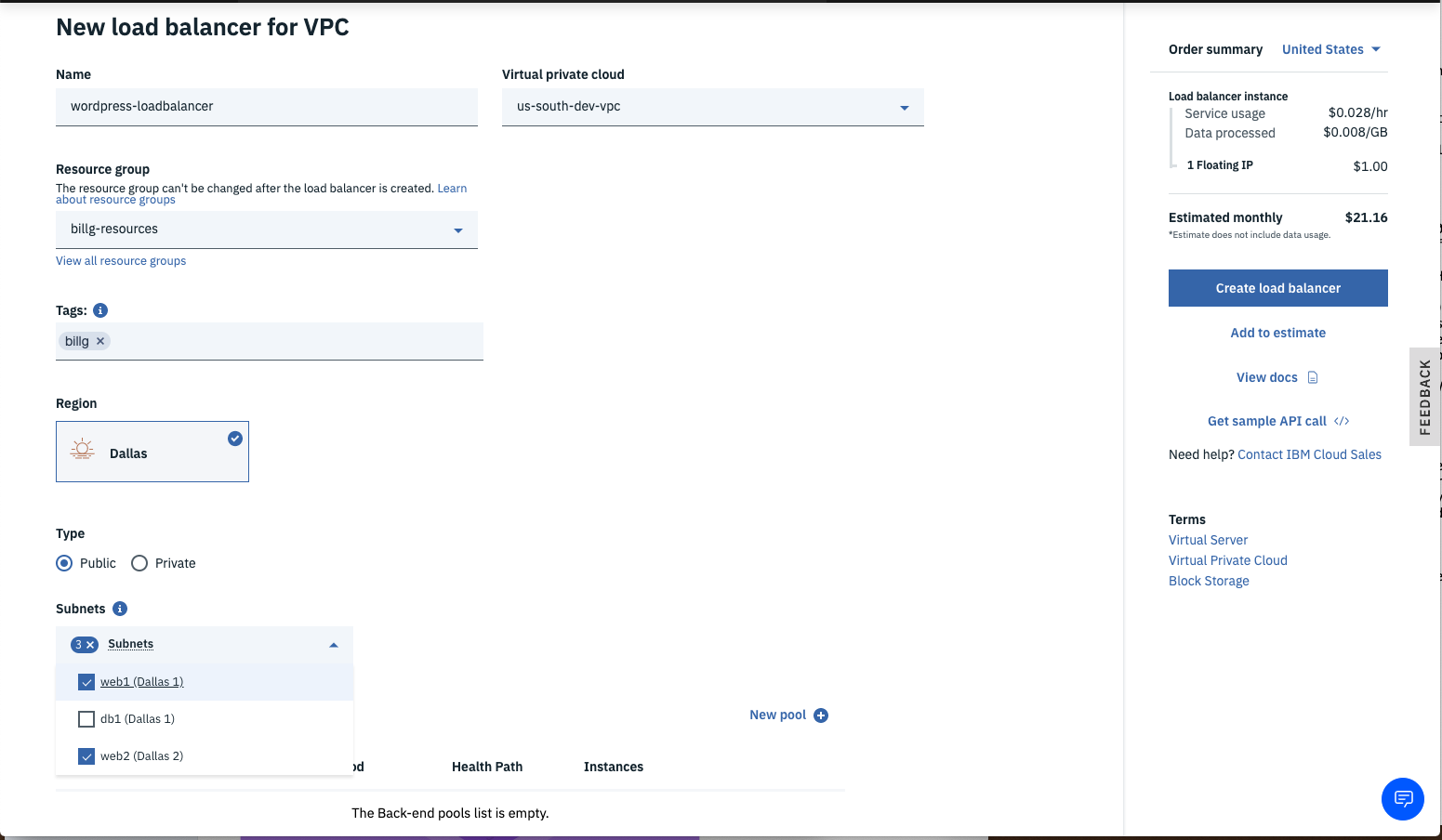
- Click the New pool link to configure the Back-end pool of services this load balancer will route to.
- Name the back-end pool (e.g.
web-servers) then enter/index.htmlfor the Health check path. You can leave the Defaults for the rest then click Save.
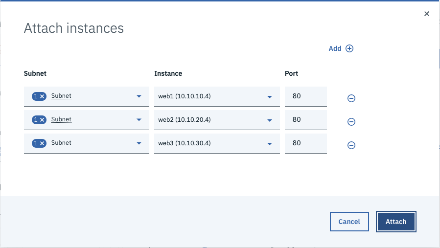
- Note: The Load Balancer can offload HTTPS encryption for you so you can use HTTP between the load balancer and the Nginx web servers. - Click the Attach link to add Instances to the Back-end pool.
- Add the
websubnets and choose thewebVSI in that subnet. Repeat this for all 3 zones of the MZR, then click the Attach button.
- Click the New listener link to specify the incoming protocol and port that will get routed to the back-end pool.
- Select HTTP for the Protocol and enter port
80for the port.
- Note: For simplicity, this tutorial just uses HTTP; for any non-trivial scenarios, the author recommends HTTPS as described here. - Ensure
web-serversis selected for the Back-end pool, then click Save. - Once everything is entered correctly, click the Create load balancer button to provision the load balancer.


Now you can test connectivity to your private web-servers thru the load balancer before going further.
-
Drill into the newly created load balancer and notice the Heath Status shows 0/3 and is Red.
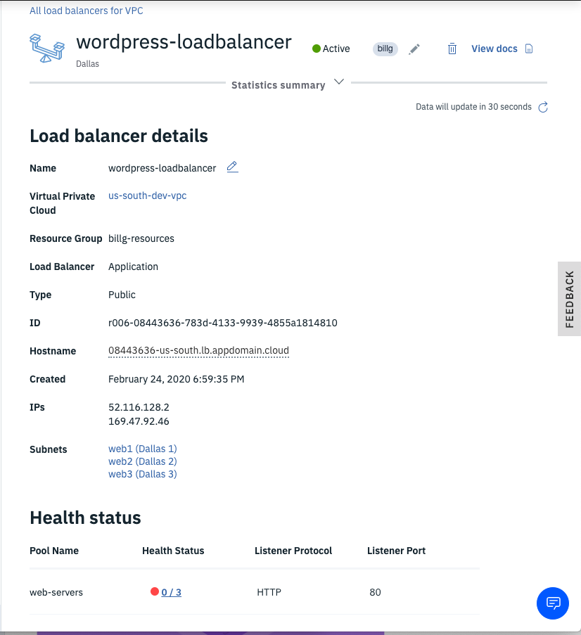
- The health status is failing as port 80 is blocked by the default-security-group.
- Add an Inbound rule for TCP port 80 from any source so you can connect to Nginx.
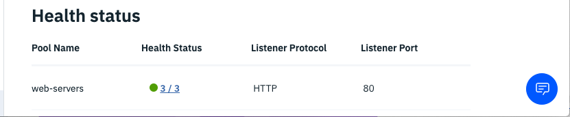
-
Go back to your load balancer and watch the Heath Status go from Red to Yellow to Green.
-
Click the Hostname dotted link to copy the public URL.
-
Paste this URL into your web browser and notice Nginx is serving up the default index page.
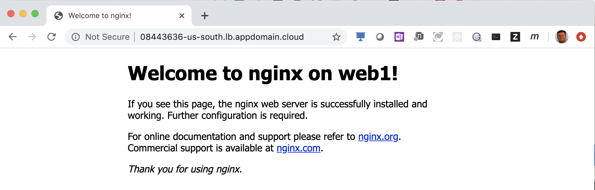
-
Refresh your browser which is pointing to the load balancer and notice the H1 element indicates each of the web servers are being routed to in a round-robin fashion.


You have successfully created part 1 of this tutorial where you built a software-defined-network using IBM's VPC service. You also built a custom subnet where you could use your own subnets. Within those subnets, you provisioned x86 Linux servers and Power9 Linux servers and verified connectivity across the VPC network. Finally, you created a VPC load balancer in front of Nginx web servers that you verified network traffic was being distributed to. Now you are ready to install some applications and test out load balancing and high availability across multiple data-centers.
Studies show the popularity of Wordpress which is used by nearly 75 million websites. The author chose Wordpress as it represents a common multi-tiered web application that is common across many workloads. While this tutorial demonstrates Wordpress HA, the process is similar with any Web, Mobile, IOT, AI based multi-tiered application.
As Wordpress depends on a database, we will start bottom-up by installing the database first to simplify dependencies. We will use MariaDB with Galera as this provides a synchronous multi-master clustered Relational Database. Read more about Galera here.
The IBM Cloud provides additional highly-available databases should you want an enterprise offering that is fully supported:
- Compose for MySQL - https://cloud.ibm.com/catalog/services/compose-for-mysql
- DB2 pureScale - https://www.ibm.com/developerworks/data/library/dmmag/DBMag_2010_Issue1/DBMag_Issue109_pureScale/index.html
- DB2 on cloud - https://cloud.ibm.com/catalog/services/db2
-
Open three terminal shells and connect to each database server (e.g.
db1) via ssh.# ssh -J root@<jump_server> root@<db_server> ssh -J root@52.116.128.59 root@10.10.11.4 ssh -J root@52.116.128.59 root@10.10.21.4 ssh -J root@52.116.128.59 root@10.10.31.4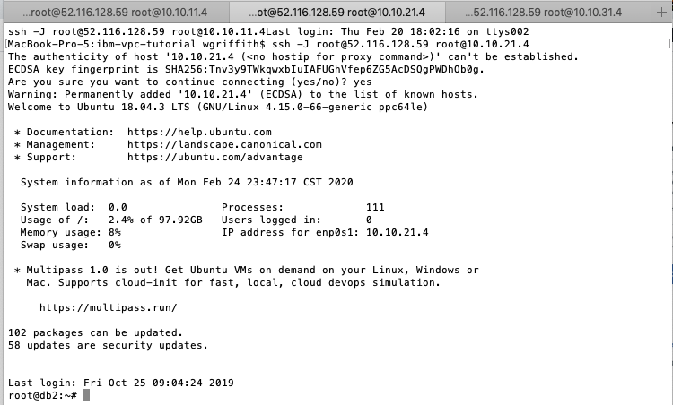
- Tip: make sure you included your public ssh key when you provisioned the VSI or you'll be prompted for the root login password.
-
Install the MariaDB 10.3 database on each
dbVSI.# MariaDB 10.3 is the default at this time on Ubuntu 18.04 apt-get -y update apt-get -y upgrade apt-get -y install mariadb-server mariadb-client galera -
Configure Galera settings on each DB server.
# Assumes MariaDB 10.3 on Ubuntu 18.04 vim /etc/mysql/mariadb.conf.d/50-server.cnf # Add the following configuration values below [mysqld] # Galera Cluster configurations (https://mariadb.com/kb/en/configuring-mariadb-galera-cluster/) wsrep_on = ON wsrep_provider = /usr/lib/galera/libgalera_smm.so # Tip: use your DB's private IP addresses (or DNS names) here wsrep_cluster_address = "gcomm://10.10.11.4,10.10.21.4,10.10.31.4" default_storage_engine = InnoDB binlog_format = row innodb_autoinc_lock_mode = 2 innodb_force_primary_key = 1 innodb_doublewrite = 1 # listen on all IPv4 interfaces bind-address = 0.0.0.0- Tip: Ensure you only have one
bind-addressproperty.
- Tip: Ensure you only have one
-
Open security group ports for Galera replication.
-
Open TCP port
4444for any node of thedb-security-group. -
Open TCP ports
4567-4568for any node of thedb-security-group.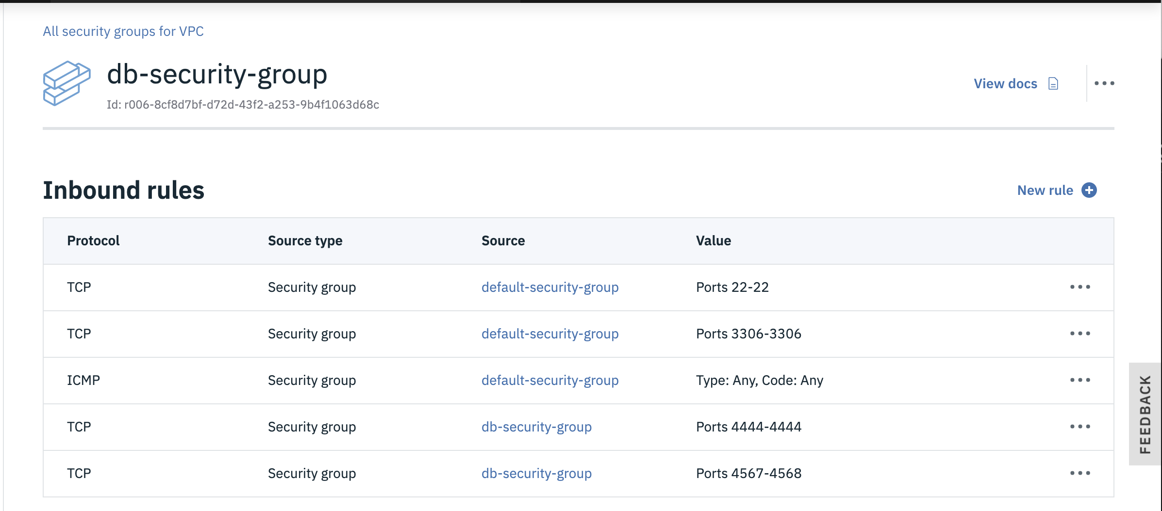
-
-
Start a new Galera cluster on your primary DB node (e.g.
db1).systemctl stop mariadb galera_new_cluster # login mysql (default password is blank) and check cluster size mysql -u root -p # run mysql command show status like 'wsrep_cluster_size';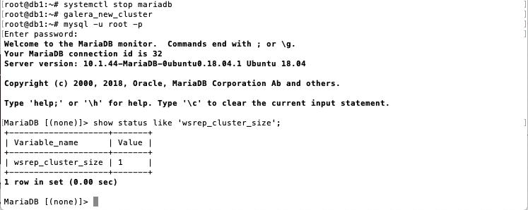
-
Join Galera cluster on remaining DB nodes.
# simply restarting mariadb will join the cluster since the config file tells this node where
systemctl restart mariadb
# on any of the nodes, run the mysql command
show status like 'wsrep_cluster_size';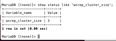
-
Verify Galera cluster is replicating.
mysql -u root -p
create database vpc_test;

# from a different node
mysql -u root -p
show databases;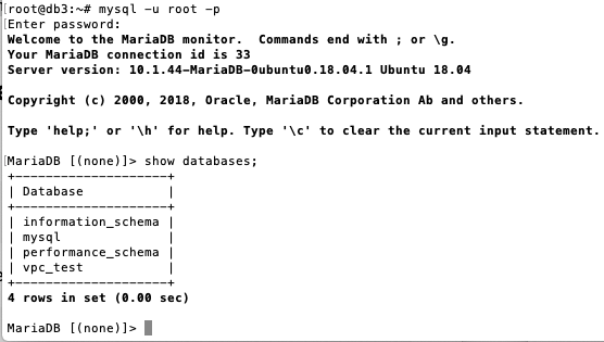
- Sweet! - Galera is replicating your database changes to the other cluster nodes.


-
Enable MariaDB at server boot time on all
dbservers.systemctl enable mariadb.service -
Update security of MariaDB on all
dbservers.mysql_secure_installation- root password =
mariaL0vesVPC - remove anonymous users =
Y - disallow root login remotely =
n - remove test database =
Y - reload priviledge tables now =
Y
- root password =
-
Create a database for
Wordpresson any of thedbserver nodes.mysql -u root -p CREATE DATABASE wordpress; # TODO: can we use wp_admin instead of root? GRANT ALL ON wordpress.* TO root@'10.10.%.%' IDENTIFIED BY 'mariaL0vesVPC' WITH GRANT OPTION; FLUSH PRIVILEGES; show databases; EXIT;
We will use Nginx as the web server with PHP for the application server functionality. You could use Apache or WebSphere Liberty or any number of Web Servers, but the author has chosen Nginx with PHP to make this tutorial accessible to all.
You could use the user-data field while provisioning the VSIs to do many of these steps during VSI provisioning (you could also burn a custom image from one VSI once it had been installed and configured as desired), but this tutorial walks thru the steps from scratch so you can see what is going on and to make debugging much easier should you run into errors during the process.
-
Open three terminals shells and connect to each web server (e.g.
web1) via ssh.# ssh -J root@<jump_server> roott@<web_server> ssh -J root@52.116.128.59 root@10.10.10.4 ssh -J root@52.116.128.59 root@10.10.20.4 ssh -J root@52.116.128.59 root@10.10.30.4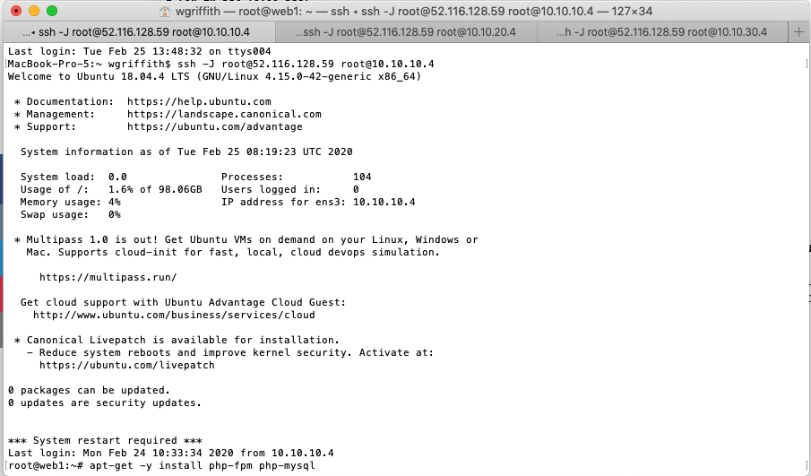
-
Update PHP libraries on all
webservers.apt-get update -y apt-get upgrade -y # keep local version of /etc/ssh/sshd_config apt-get -y install php-fpm php-mysql # common libraries needed for wordpress apt install -y php-curl php-gd php-intl php-mbstring php-soap php-xml php-xmlrpc php-zip php -v # to confirm 7.2+ is installed # stop php and nginx systemctl stop php7.2-fpm systemctl stop nginx -
Configure Nginx for PHP on each
webserver.-
Modify the default Nginx configuration (e.g.
vi /etc/nginx/sites-available/default).root@web2:~# !vi vi /etc/nginx/sites-available/default -
Add index.php to the list of startup pages.
index index.php index.html index.htm index.nginx-debian.html; -
Uncomment FastCGI server config and change php to 7.2.
location ~ \.php$ { include snippets/fastcgi-php.conf; fastcgi_pass unix:/run/php/php7.2-fpm.sock; } -
Uncomment .ht stanza to deny access.
 location ~ /\.ht {
 	deny all;
 }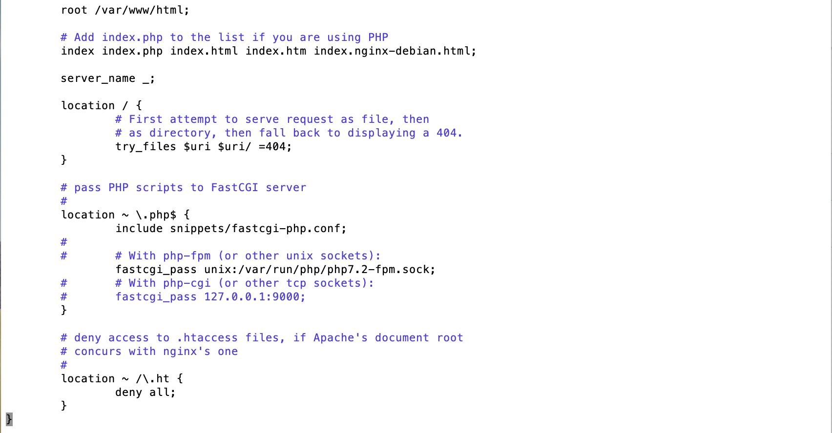
-
Verify Nginx config.
root@web2:~# nginx -t nginx: the configuration file /etc/nginx/nginx.conf syntax is ok nginx: configuration file /etc/nginx/nginx.conf test is successful root@web2:~# -
Ensure nginx and php-fpm are started.
 systemctl start nginx
 systemctl reload nginx
 systemctl start php7.2-fpm
-


- Create a php page on each
webserver.echo "<?php phpinfo(); ?>" > /var/www/html/info.php # test PHP curl localhost/info.php | tail -20
We will use GlusterFS to provide an active-active disk cluster for our Wordpress files so we can tolerate a complete data-center outage without loss of data or availability.
- Install glusterFS on each
webserver.apt update -y apt upgrade -y add-apt-repository -y ppa:gluster/glusterfs-7 apt install -y glusterfs-server - Mount local disk for glusterFS.
You first need to create anxfsfilesystem on the disk (i.e. theweb1-www-voldata volume) that is attached to thewebserver.# find your disk lsblk # block devices output NAME MAJ:MIN RM SIZE RO TYPE MOUNTPOINT vda 252:0 0 100G 0 disk ├─vda1 252:1 0 256M 0 part /boot └─vda2 252:2 0 99.8G 0 part / vdb 252:16 0 100G 0 disk vdc 252:32 0 370K 0 disk vdd 252:48 0 44K 0 disk [SWAP]- Notice the
vdbat 100G is the extra data volume (i.e.web1-www-vol) that you created during provisioning thewebVSI.
- Notice the
-
Format the disk using the
xfsfilesystem type.mkfs.xfs /dev/vdb- You could partition the disk or use a logical volume manager before adding a filesystem, but we just format the whole drive to make things easy.
-
Mount the disk
# first mount the block device locally, then you can mount the glusterFS mkdir -p /gluster/wordpress echo '/dev/vdb /gluster/wordpress xfs defaults 0 0' >> /etc/fstab mount -a mkdir -p /gluster/wordpress/brick01- Change brick name to match server number (e.g. brick02 for
web2).
- Change brick name to match server number (e.g. brick02 for
-
Repeat step 2 on all
webservers.
-
Configure Gluster
systemctl enable glusterd -
Add nodes to trusted storage pool from one node only.
# from web1
gluster peer probe 10.10.20.4
gluster peer probe 10.10.30.4
# verify peer trust
gluster peer status
gluster pool list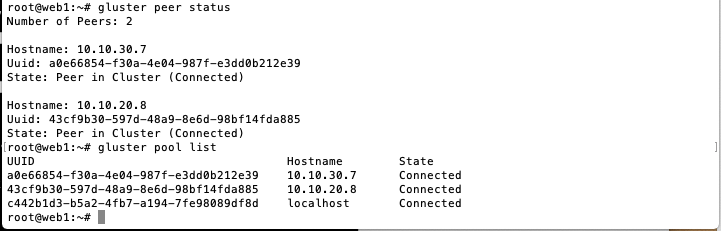
-
Create Gluster Volume from one node only.
gluster volume create wordpress-vol replica 3 10.10.10.4:/gluster/wordpress/brick01 10.10.20.4:/gluster/wordpress/brick02 10.10.30.4:/gluster/wordpress/brick03 # start the volume gluster volume start wordpress-vol root@web1:~# gluster volume status wordpress-vol Status of volume: wordpress-vol Gluster process TCP Port RDMA Port Online Pid ------------------------------------------------------------------------------ Brick 10.10.10.8:/gluster/wordpress/brick01 /volume 49152 0 Y 20032 Brick 10.10.20.8:/gluster/wordpress/brick02 /volume 49152 0 Y 19315 Brick 10.10.30.7:/gluster/wordpress/brick03 /volume 49152 0 Y 19023 Self-heal Daemon on localhost N/A N/A Y 20053 Self-heal Daemon on 10.10.20.8 N/A N/A Y 19336 Self-heal Daemon on 10.10.30.7 N/A N/A Y 19044 Task Status of Volume wordpress-vol ------------------------------------------------------------------------------ There are no active volume tasks- Ensure you have an Inbound security group rule to allow all traffic (or TCP port 49152 for Gluster) among VSIs of the same security group.
- Ensure you have an Inbound security group rule to allow all traffic (or TCP port 49152 for Gluster) among VSIs of the same security group.


- Only allow
webnodes to mount the Gluster volume.# run from one node only gluster volume set wordpress-vol auth.allow 10.10.10.4,10.10.20.4,10.10.30.4
-
Mount the GlusterFS volume locally on each
webserver.# stop nginx systemctl stop nginx mv /var/www/html{,.orig} mkdir /var/www/html echo 'localhost:/wordpress-vol /var/www/html glusterfs defaults,_netdev 0 0' >> /etc/fstab mount -a df -h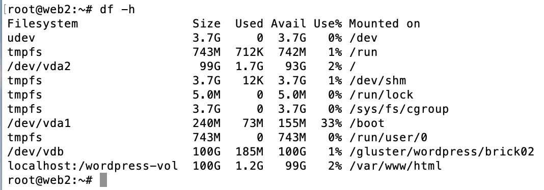
-
Test Gluster replication from one
webserver node.echo 'Hello Gluster!' > /var/www/html/index.html systemctl start nginx curl localhost -
Start Nginx on the rest of the
webserver nodes.systemctl start nginx curl localhost

Since GlusterFS will replicate /var/www/html to all of the web servers, you only need to install Wordpress on one node.
-
Download and install Wordpress on one of the
webservers.cd /tmp && wget https://wordpress.org/latest.tar.gz tar -xvf /tmp/latest.tar.gz # put wordpress in html to make things easy cp -r /tmp/wordpress/* /var/www/html/ rm -rf /tmp/wordpress rm -rf /tmp/latest.tar.gz chown -R www-data:www-data /var/www/html/wp-content chmod -R 755 /var/www/html/wp-content mv /var/www/html/wp-config-sample.php /var/www/html/wp-config.php -
Update
/etc/hostswith the database IP address on eachwebnode.-
Use the same database name (e.g.
mariadb) on allwebservers, but change the IP Address to the correspondingdbserver in the same zone.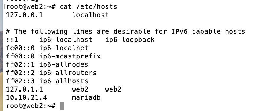
-
-
Configure Wordpress on one node only to point to db servers.
- Get wordpress secret-keys using
# curl https://api.wordpress.org/secret-key/1.1/salt/ - Copy them into wp-config.php
- Edit
/var/www/html/wp-config.phpand set the DB parameters
define('DB_NAME', 'wordpress');
define('DB_USER', 'root');  # TODO:  can I use db_admin
define('DB_PASSWORD', 'mariaL0vesVPC');
define('DB_HOST', 'mariadb'); # use private load balancer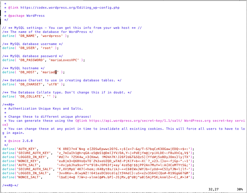
- Get wordpress secret-keys using
-
Start nginx on each
webserver.systemctl start nginx systemctl reload nginx systemctl start php7.2-fpm -
Verify Wordpress
- Open the
web-load-balancerhostname (e.g.956071b2-us-south.lb.appdomain.cloud) in your web browser.
- Open the
-
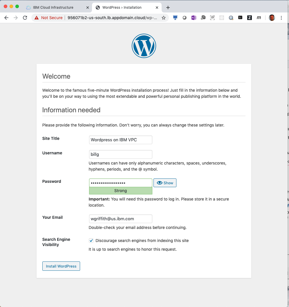
Setup Wordpress


- Enter
Wordpress on IBM VPCfor the Site Title. - Enter
<an admin userID>for the Username field. - Enter a strong
password. - Enter your
admin's email address. - Click to
Discourage search engines.... - Click Install WordPress.

- Add a Wordpress Post
- Login to Wordpress
- Click Posts link, then click Add New button.
- Add your post.
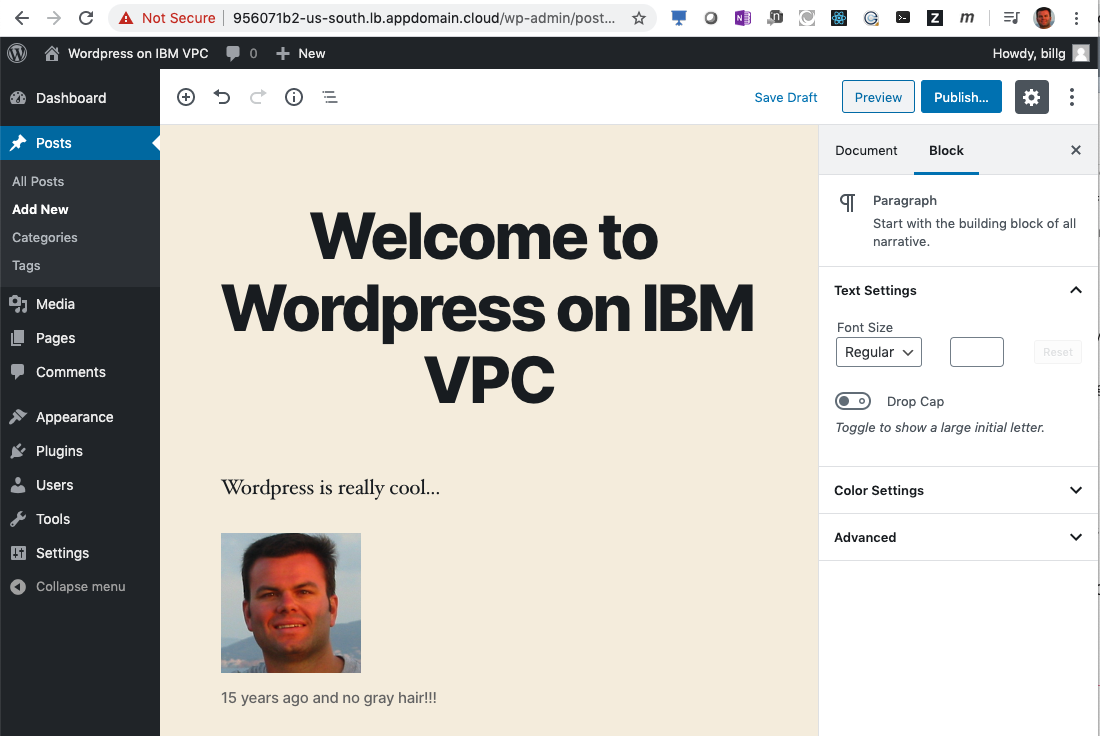
- Publish your post.

- Verify Wordpress High Availability
- From
web1do a find command to verify your image was uploaded in your post.
  find /var/www/html/wp-content/uploads/
  /var/www/html/wp-content/uploads/
  /var/www/html/wp-content/uploads/2020
  /var/www/html/wp-content/uploads/2020/03
  /var/www/html/wp-content/uploads/2020/03/billface-1.png
- Repeat the
findcommand from anotherwebnode and you'll see the image is there also.
Now that you have a highly available 3 zone web application, you can now test various failures and ensure your web application continues to process user requests.
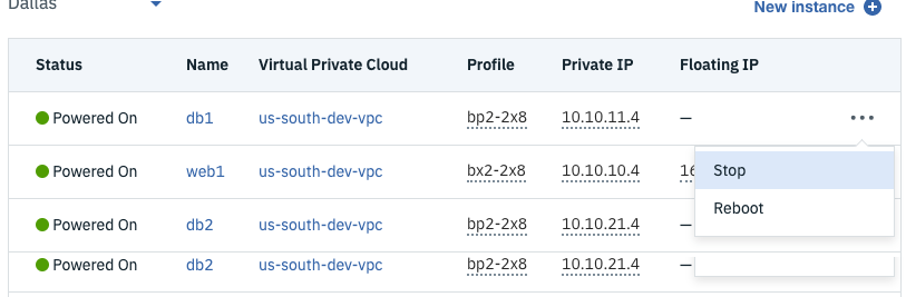
Shutdown one of the db nodes and verify Wordpress continues to work.
- Click the Virtual server instances link in the VPC Infrastructure section of the IBM Cloud console.
- Click ellipsis next to
db1and choose Stop.
- Refresh Wordpress URL (i.e. Load Balancer hostname) a few times to cycle thru to the failing DB.
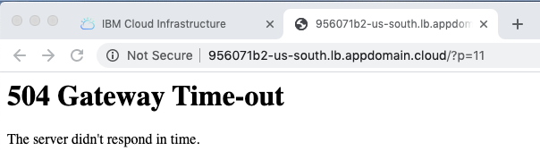
- Notice you get an outage, even though you have 2 other DBs. You need to tell the Load Balancer to not route traffic to a
webserver IF thedbfor that zone is down.
- Notice you get an outage, even though you have 2 other DBs. You need to tell the Load Balancer to not route traffic to a
- Edit the
web-serversBack-end pool in yourwordpress-load-balancerand change the Health check value from/index.htmlto/index.php.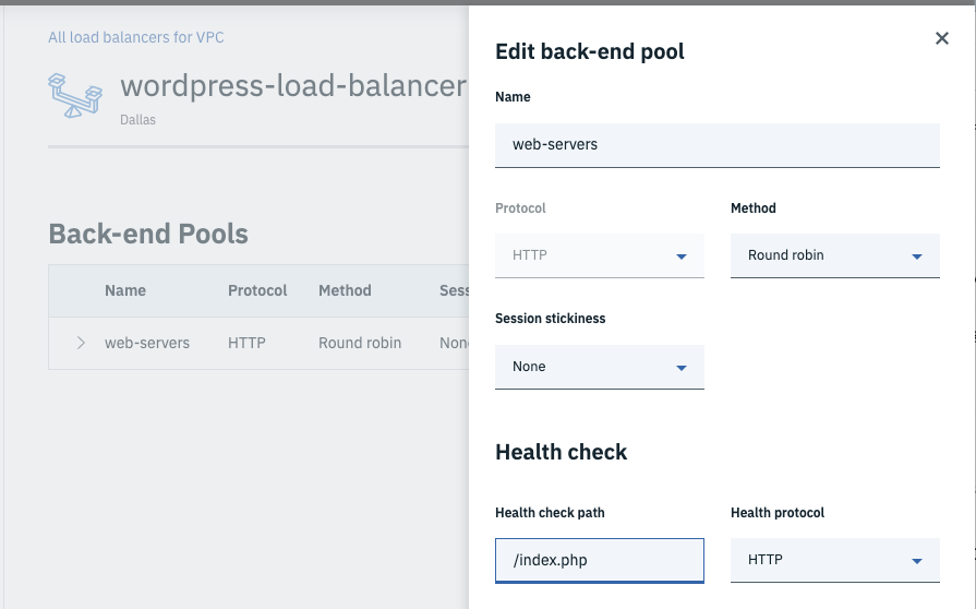
- Now the Load Balancer will know not to route traffic to the failing
webserver if Nginx is down or if the database is down.
- Now the Load Balancer will know not to route traffic to the failing
- Try refreshing your browser a few times and notice that the 504 Gateway Time-out error doesn't reappear.
- Restart the
dbnode that you stopped earlier.


Shutdown one of the web nodes and verify Wordpress continues to work.
-
Stop a
webnode if a different zone than the zone from yourdbtest. -
Refresh your browser and notice you don't see any errors; yet if you check the
wordpress-load-balancer, you'll notice only 2/3 web-servers are up.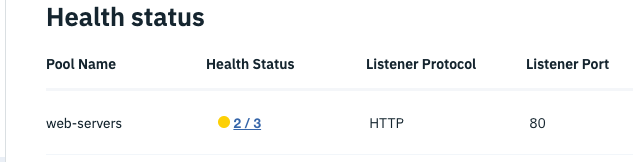
-
Edit your previous post and upload a new image.
-
Examine the filesystem of each
webnode and verify uploads are still working after the db failure and the web failure.root@web3:~# find /var/www/html/wp-content/uploads/ /var/www/html/wp-content/uploads/ /var/www/html/wp-content/uploads/2020 /var/www/html/wp-content/uploads/2020/03 /var/www/html/wp-content/uploads/2020/03/billface-1.png /var/www/html/wp-content/uploads/2020/03/wordpress_healthcheck.png /var/www/html/wp-content/uploads/2020/03/wordpress_healthcheck-300x187.png /var/www/html/wp-content/uploads/2020/03/wordpress_healthcheck-150x150.png /var/www/html/wp-content/uploads/2020/03/wordpress_healthcheck-768x479.png- Examine the db server to verify your update is persisting.
root@db3:~# mysql -u root -p
MariaDB [(none)]> show databases;
MariaDB [(none)]> use wordpress;
MariaDB [wordpress]> show tables;
MariaDB [wordpress]> select * from wp_posts;

You have to remove things in order of dependency. You can of course do this from command line so you could have a deleteVPC script, but for the sake of completeness, we'll use the IBM Cloud UI.
- Release any Floating IP addresses from your VSIs.
- Stop all VSIs of your VPC.
- Delete all VSIs from your VPC.
- Delete all Load Balancers from your VPC.
- Delete all subnets from your VPC.
- Verify all Block storage volumes are deleted from your VPC.
- Finally, delete your custom VPC.
This has been a long tutorial, but our hope is that you have a better understanding of the IBM Public Cloud and how you can configure highly available multi-tiered applications within a secure Virtual Private Cloud (VPC) to serve your transformational objectives.
We look forward to your workloads joining the IBM Cloud family. :)
The postings on this site are my own and don't necessarily represent IBM's positions, strategies or opinions.