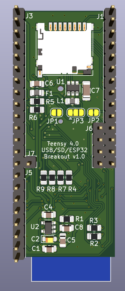
A jumbo breakout board with ESP32, USB-A host and microSD connectors to mate with the Teensy 4 Header Breakout Board.
Additionally, the board includes a space for RTC Battery Holder and provides another Teensy reset/programming button (since it covers up the one on the Teensy).
It's designed to mount above or below the Teensy 4 and Header Breakout board on a relatively tall header.
Designed in KiCad.
- Status: Version 1.0 board ordered
- OSHPark (https://oshpark.com/projects/xaSKCWHX)
- Download bom/ibom.html and view it with web browser to see bill of materials and placement information.
- Three jumpers on the back:
- JP1 - Short to use Teensy 3.3v to power ESP32 (instead of onboard 3.3v regulator)
- JP3 - Cut left side, bridge right side to disable D27 as USB Power Enable
- JP2 - Cut to disable D29 as SD card detect
- J1 and J3 connect to the Teensy 4 Header Breakout Board pins via a header
- J5 is optional and provides access to the onboard 3.3v regulator
- J6 & J7 are optional and provide connection to the corresponding pins directly below on Teensy. These connect the ESP32 SPI to the Teensy SPI port for high-speed goodness. Should be compatible with the Adafruit Airlift firmware.
- J2 is a USB-A host connector
- J4 is a MicroSD push-pull connector
- Teensy programming button
- Socket for 12mm lithium backup batter for RTC
- RGB and White LEDs connected to ESP32 for additional status
J1 - Left Side Pinout:
- Teensy D34 / SD DAT1
- Teensy D35 / SD DAT0
- GND
- Teensy D36 / SD CLK
- Teensy 3.3v
- Teensy D37 / SD CMD
- Teensy D38 / SD DAT3
- Teensy D39 / SD DAT2
- Teensy D29 / Card Detect
- Teensy D31 (unused)
- Teensy D33 (unused)
- Teensy D32 (unused)
- Teensy D30 (unused)
- Teensy VBAT (battery backup)
J3 - Right Side Pinout:
- Teensy VUSB
- Teensy USB Host D-
- Teensy USB Host D+
- GND
- GND
- Teensy D27/USB Power EN
- Teensy D25/ESP32 IO1 (Serial RX)
- Teensy D26 / ESP32 IO0 (Boot Mode)
- Teensy D28 / ESP32 EN (Reset)
- Teensy D24 / ESP IO3 (Serial TX)
- Teensy 3.3v
- GND
- Teensy Program
- Teensy On/Off (unused)
J5 - Optional additional pins
- GND
- 3.3v from regulator on breakout board
- ESP32 IO2
- ESP32 IO4
- ESP32 IO12
- ESP32 IO13
- ESP32 IO15
- ESP32 IO16
J6 - SPI between ESP32 and Teensy
- Teensy D9 / ESP32 IO32 (Busy)
- Teensy D10 / ESP32 IO5 (CS)
- Teensy D11 / ESP32 IO14 (MOSI)
- Teensy D12 / ESP32 IO23 (MISO)
J7 - SPI between ESP32 and Teensy (cont.)
- Teensy D13 / ESP32 IO18 (SCK)


