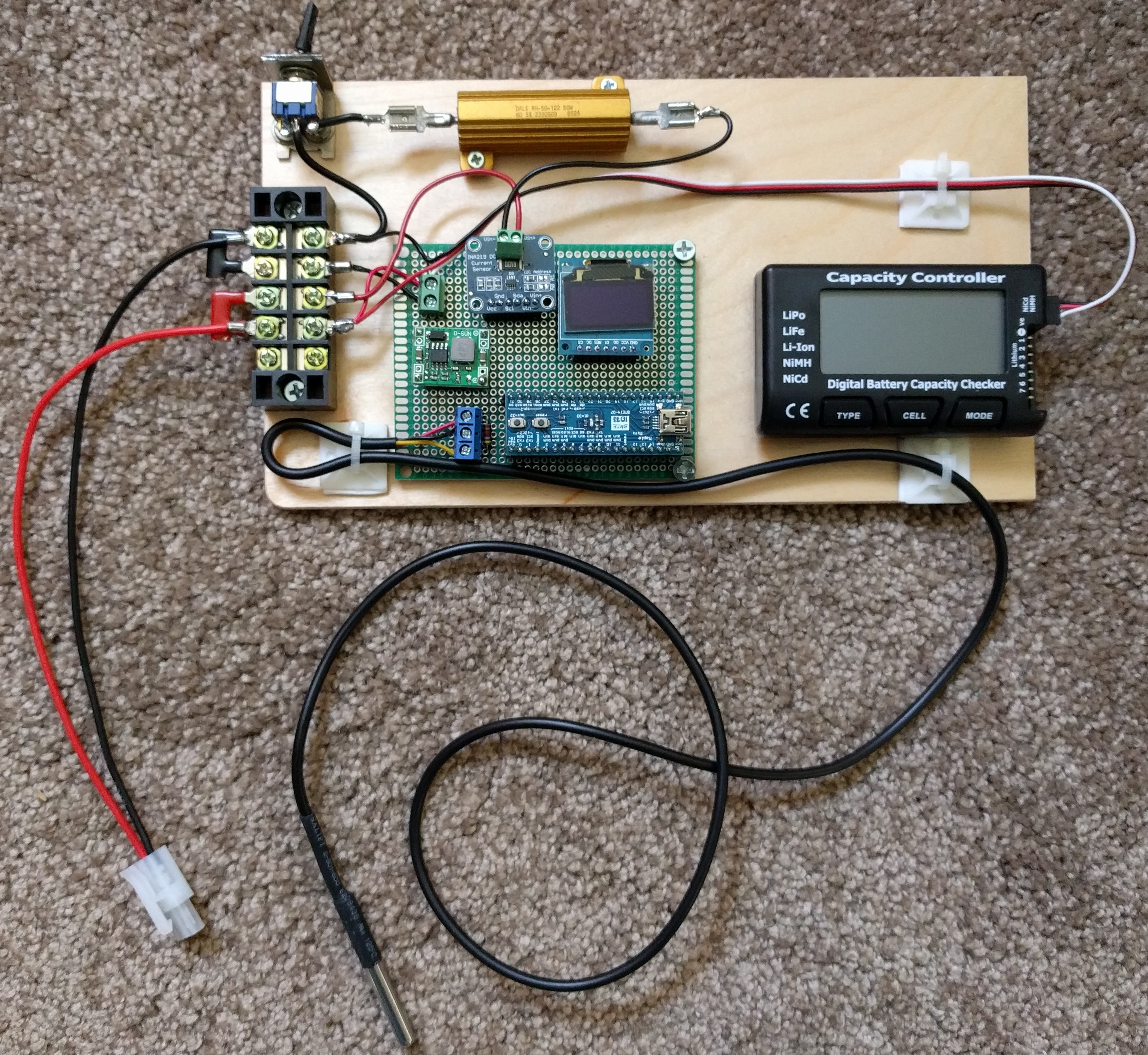
This project was developed to allow measurement of voltage, current and watts from > 5 to < 20 volts DC. Maximum current applied must be < 3200 mA.
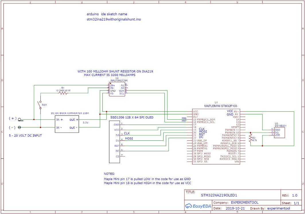
I will explain the operation of the circuit board first. So refer to the pdf of the schematic diagram during this explanation.
The first component to discuss is the DC-DC buck converter utilizing a 1584 IC. It is set up to take input voltages from > 5 volts to < 20 volts DC and the output will be 3.3 volts DC with a current capability of around 1 amp. This 3.3 volt output will be used to power up all of the active devices on the circuit board.
The microcontroller used is an STM32F103 maple mini or 'bluepill'. This ARM device does not come with a USB compatible bootloader. You must use an FTDI 3.3V serial to USB or load the appropriate USB bootloader using the STM32 loader program. I will not get into how to perform these functions as they are readily available. I used the usb bootloader with the Arduino IDE for programming this controller. The Arduino IDE must also have the appropriate changes performed to allow programming of the STM32F103 maple mini/bluepill. The C++ Arduino code program loaded on this controller is named stm32ina219oled1.ino and is included in this project file with the appropriate library files. The ino file contains many comments to help in the understanding of how the device works.
The next device is the ina219 voltage measurement board. It uses I2C communication with the STM32 microcontroller to supply the bus voltage and current. It has a 100 milliohm resistor onboard that is used as a current shunt. For example; if the current supplied from the source is 3200 mA, the voltage across the shunt would be 320 mV or the max that this device is capable of reading with the 100 milliohm resistor. You could remove the 100 milliohm resistor and put in an external shunt to measure larger current levels. The adafruit ina219 libraries have to be changed to do this.
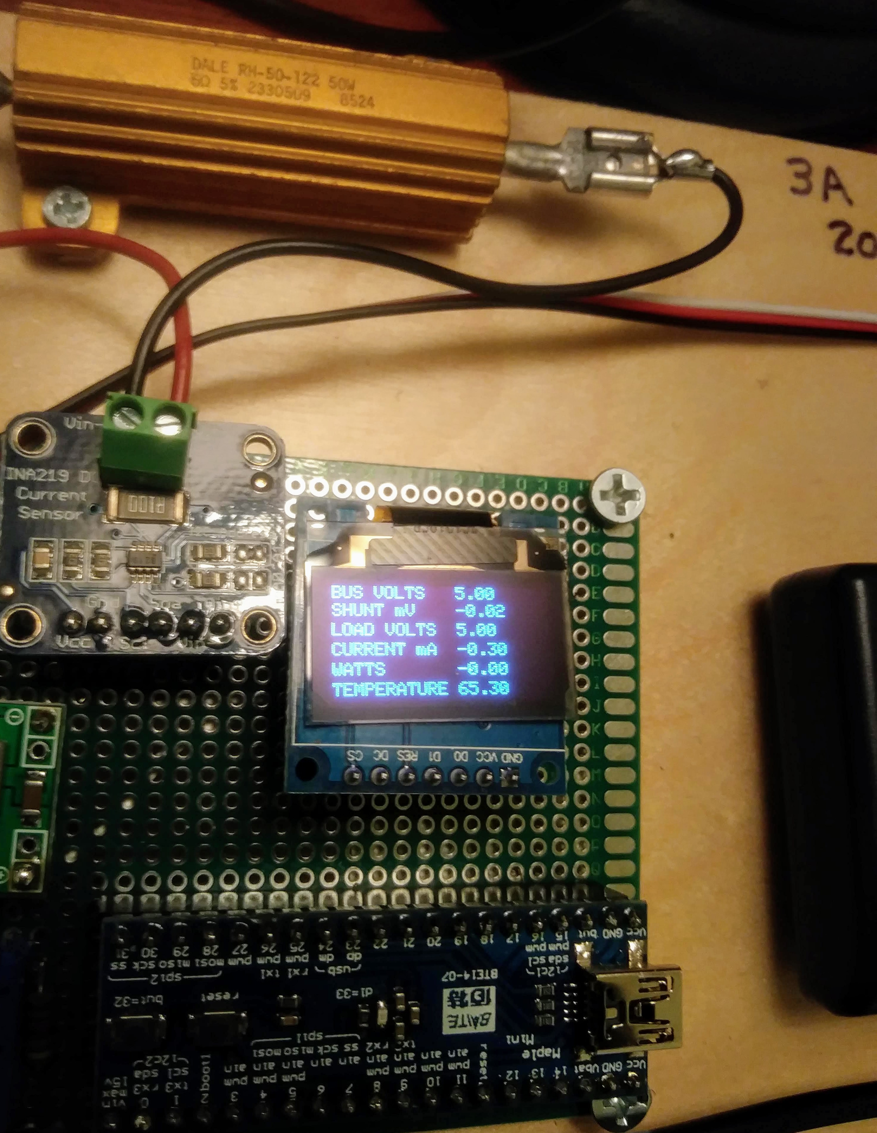
The next device is the ssd1306 oled display. It is using spi communication with the STM32 microcontroller. By perusing the ino program you will determine the text that will be displayed. Parameters such as bus voltage, current, watts and temperature are included.
The last device is a ds18b20 one wire temperature sensor. It obviously uses 'one wire' as the communication protocol with the STM32 microcontroller. I included this device just to see how many devices I could utilize in this project. It is set up for degrees F.
So, to test a battery with this device, it has to be at least 5 volts dc. This minimum is required so the dc-dc buck converter has enough head room to get a 3.3 volt output for the devices on the circuit board.
Note: The STM32 microcontroller only takes a new reading every three seconds. Lets say we use a NiMH 10 cell battery with a nominal 12 volts output. Preliminary measurements made with this voltage has the circuitry drawing around 150 mA. With the 6 ohm currrent test resistor switch R1 in the open position the bus voltage should display 12 volts and the current and watts would be zero as the current only measures the flow through the 6 ohm test resistor. Closing the R1 switch should cause the current to rise up to around 2000 mA and the bus voltage to drop. Only leave R1 closed for around a 25 second duration. This voltage drop will give you an indication of battery condition and capacity. You can make up a chart for logging to test a battery under various conditions of charge and age.
As always, please use this information only if you are competent in the use of electronics and the safety practices necessary.


