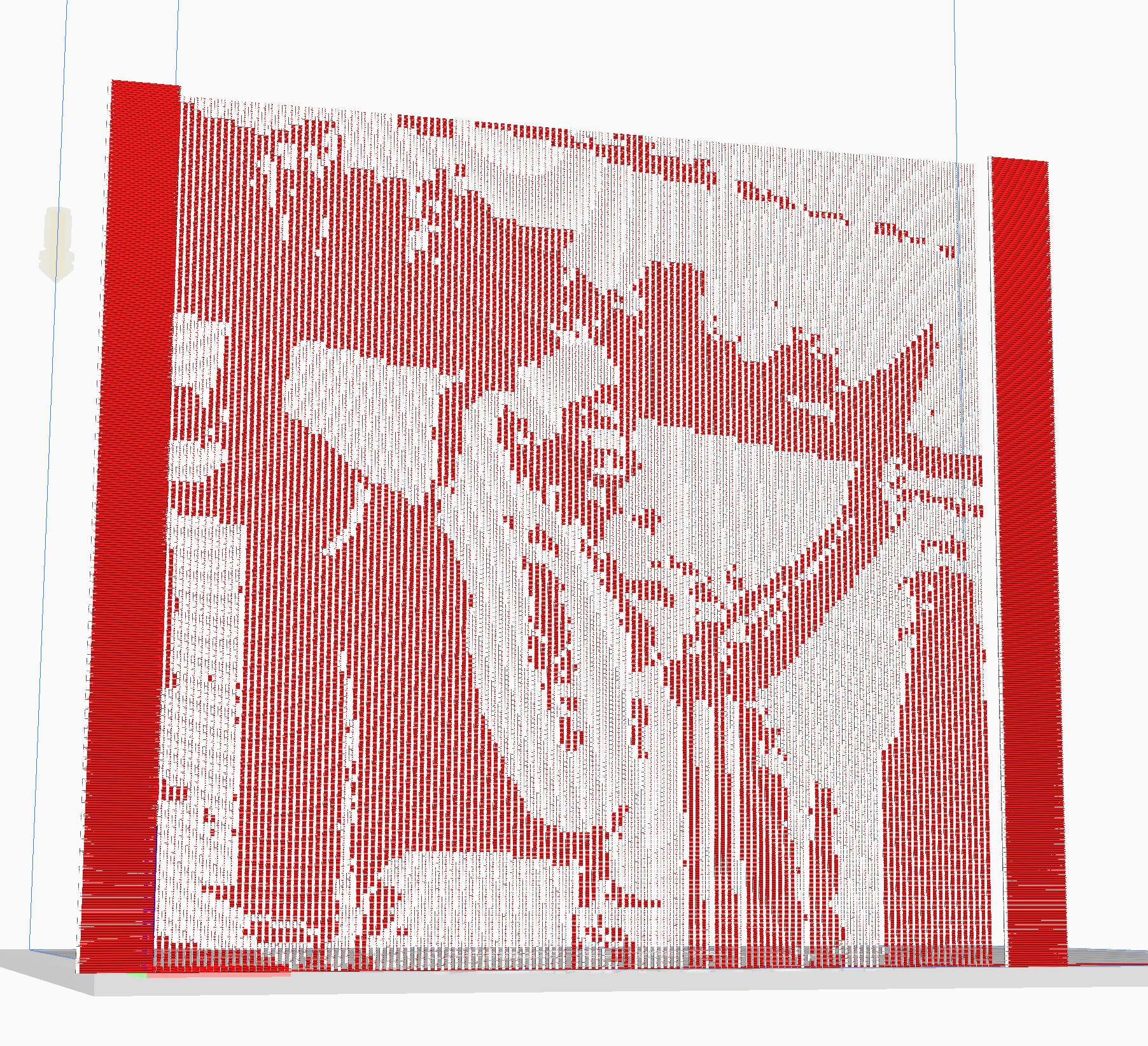
Image2Gcode is a demo created for my final project in Prof. Jennifer Jacobs' MAT594X Computational Fabrication course at UC Santa Barbara. The goal of the project is to create a gcode parser that takes in a jpeg as an input, resizes it, builds a frame around it and prints it out in a single sheet vertically. The image is comprised of variably extruded plastic. This project was inspired by the DefeXtiles project at MIT's Media Lab, with some key differences in methodology. I'm very grateful for the support and feedback I received in the process of working on this project from the project's contact Jack Forman.
This project largely became a speculative exploration of the possibilities of controlling the minute movements of a 3D printer using a customized gcode parser and I hope to continue working on it.
- Is it possible to print a 2D image by varying extrusion on an FDM printer?
- What is gained by parsing gcode via writing custom code?
There were several technologies that were key to my project that I explored on top of the core topics we learned in class for my final project.
The most crucial technology and the core of this project was a Gcode parser that was given to us by Prof. Jacobs which was originally writen in Python. My work involved porting this code to C++ and adding a few features that would enable me to print the images. This is not a general purpose parser, but is rather a customized parser that is tailored to the task of printing a single row of plastic and variable extrusion levels.
When creating a parser for Gcode it's important to have a specification as your target. Because we are using the Ender 3 Pro printer, we used the Marlin Gcode specification, which is very well-documented and easy to follow.
As I was working on this project, there were a few features I added to the parser I was given out of necessity:
- More comments in the Gcode to help me understand where certain things were happening.
- The print is centered on the platform for optimal bed flatness.
- The print is presented by the printer by turning the heated bed and nozzle off, raising the print nozzle up, and pushing the print forward.
- The parser reads a data structure full of booleans to see whether it should be printing or just moving.
- The printer starts out by printing a long strip of plastic to ensure plastic is extruding properly. This improved success of the first layer.
Here are some examples of the types of comments I added to the code for clarity:
; 202162
M140 S65 ; Set Bed Temperature
M105
M190 S65 ; Wait for Bed Temperature
M104 S210 ; Set Nozzle Temperature
M105
M109 S210 ; Wait for Nozzle Temperature
G28
M83
G90
G1 F300 Z0.20 ; set Z-offset
G1 F1200 X210.00 Y10.00 E2.19516891
G1 F1200 X10.00 Y11.00 E2.19516891
G1 F1200 E-6.00000000 ; Retraction
G0 F6000 X46.00 Y110.00 ; Move to print origin
G92 X0.00 Y0.00 Z0.00 ; Set this point to 0,0,0 in coordinate space
G1 F300 Z0.330000
G0 F9000 X-10.00 Y-5.00
G1 F1200 E6.00000000 ; Recover
[...]
The goal of using and learning OpenCV was more of a pragmatic one. While it's overpowered for my current use case, learning how to use it affords the possibility of working with an extremely powerful library in the future. There are a number of challenges to overcome when using OpenCV for the first time that I needed to overcome. Thankfully the documentation is compehensive:
- Compiling OpenCV for the first time can be confusing and take a long time.
- OpenCV's data structures are unique and I needed to familiarize myself with them.
- It can be unclear how OpenCV actually stores the data you give it, so manipulating the data is error prone.
- Even though it is powerful, I found myself writing logic for doing simple things, like a distance function or resizing an image based on a single side. One could take an entire course on OpenCV and only begin to be familiar with its intricacies.
Before going into too much detail, it is important to point people to two key pieces of software that alleviated the biggest pain point of a project like this that involves writing code to achieve a visual output using external hardware. Simulation is everything and will save you time. In order to simulate my projects, I was able to use two key pieces of software effectively:
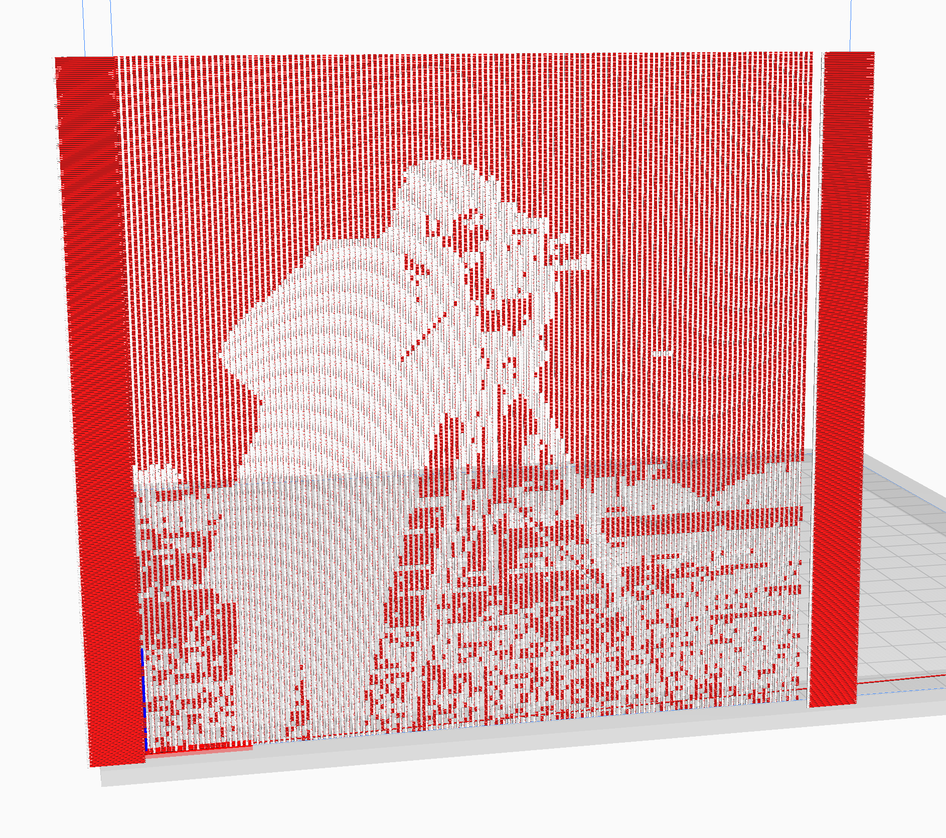
- Ultimaker Cura: This piece of free software will simulate Gcode very effectively. While it is not exact for custom Gcode that wasn't parsed by its own parser, it is very effective in giving a general idea of what printed output is like. The biggest benefit is that Cura simulates extrusion rates in its visualization.Note: Cura does not adhere to any coordinate system changes, so objects may be placed incorrectly if you modify the coordinate system at all using the G92 Gcode command.
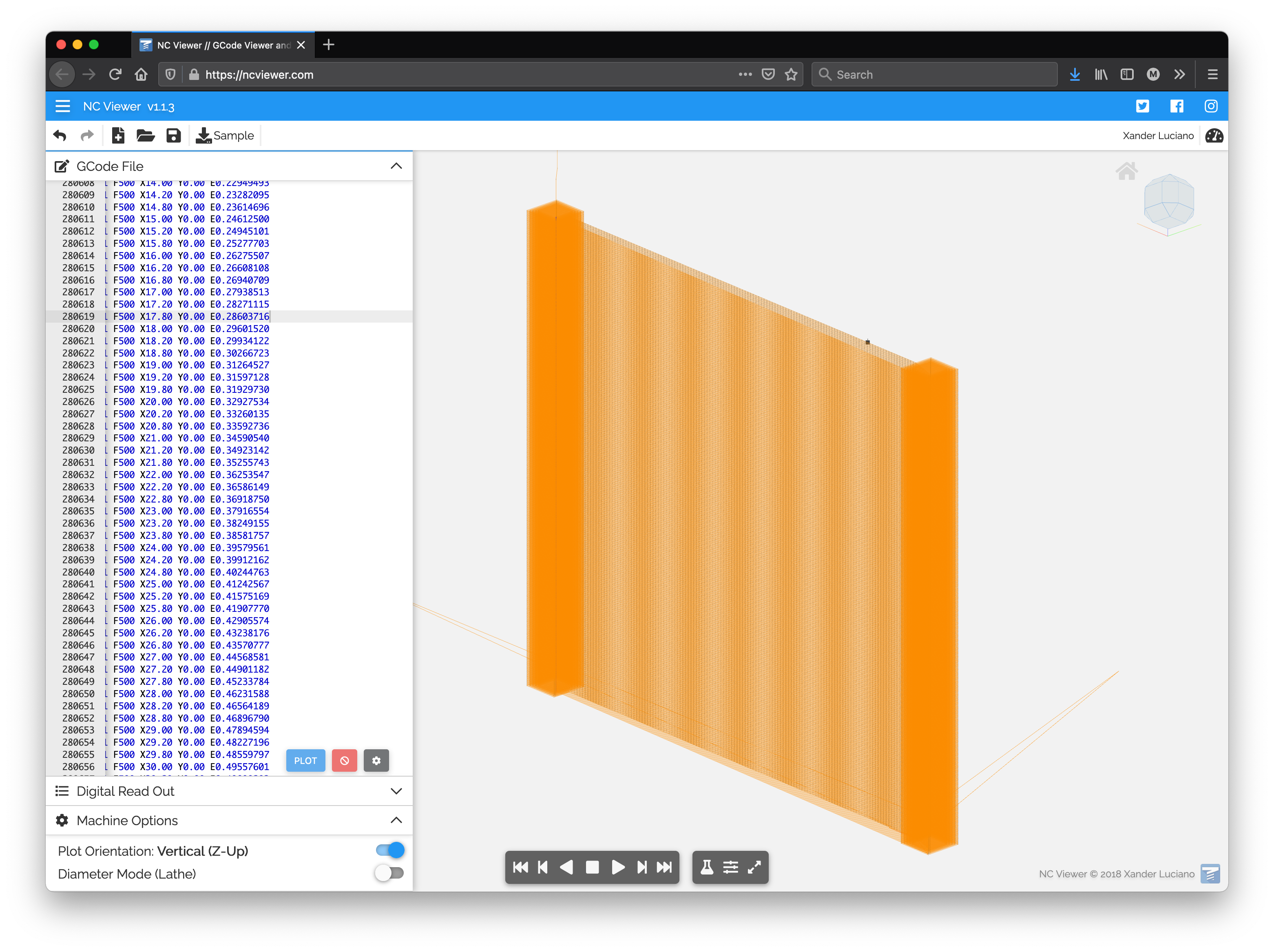
- NC Viewer: This is a web-based platform for visualizing Gcode pathways. It works very well and I was able to quickly check whether my general paths were correct before moving to the printer. The only drawback to this system is that it does not visualize extrusion rates.
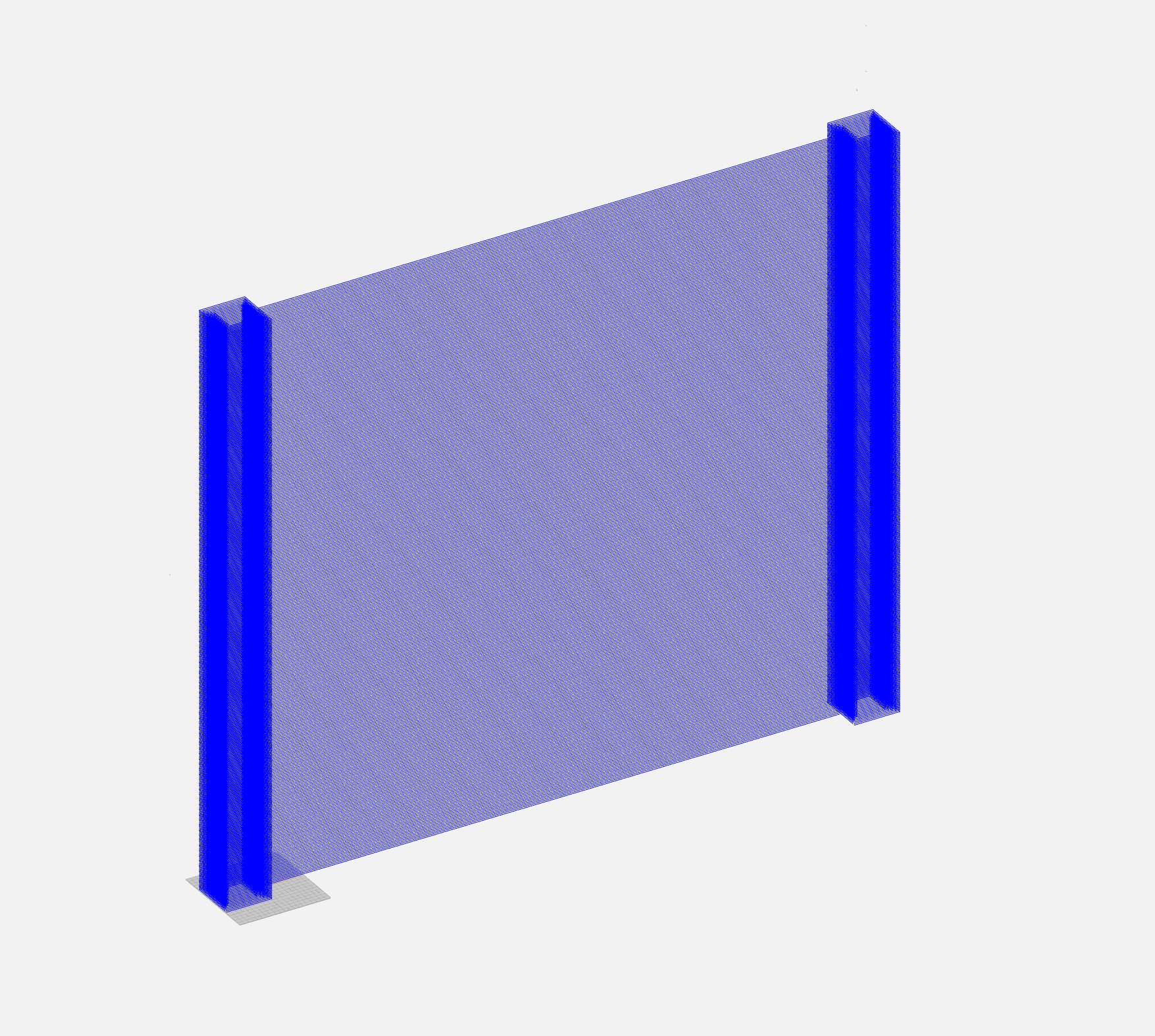
From the outset, the goal of this project was to print a 128 pixel-wide image vertically in a single row of plastic between two pillars that would hold the image together. The single layer of plastic would form a kind of textile, similar to lace, that would have an image on it.
The basic concept can be seen here:
One of the big lessons from this project was learning to think beyond discrete pixels, as I've always been used to thinking of images. 3D printing is an organic process determined by melting plastic. There are not discrete extrusion values, there is only the range of what happens when a variable is changed.
Moving from discrete pictures to a way of thinking that was more like weaving is what enables this process to work.
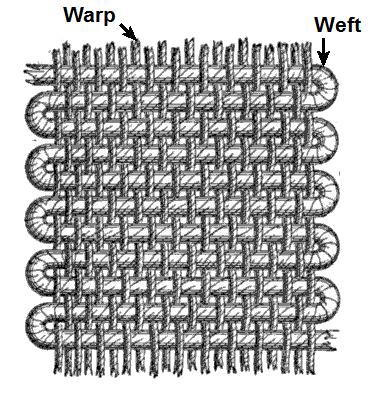
[Image Credit: By Alfred Barlow, Ryj, PKM - Adapted from The History and Principles of Weaving by Hand and by Power by , 1878, S. Low, Marston, Searle & Rivington, London., CC BY-SA 3.0,https://commons.wikimedia.org/w/index.php?curid=94725908]
In weaving the warp and weft are what give a textile its strength. The warp is the vertical thread element and the weft is the horizontal element. They are both interwoven. The same metaphor can be applied to 3D printing and this metaphor has been used in multiple projects in the past [1, 2].
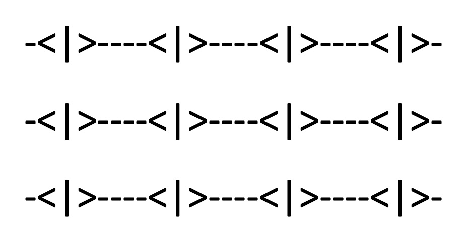
The warp and weft metaphor gives us a way of translating discrete pixels into 3D printed space. The image below is the key to understanding this process:
Let's pretend the image above is a 3x3 pixel image that has been prepared to be 3D printed. The |>, <|>, and <| characters represent the warp of the image. These are thick areas that are consistent in their size and allow the image to stick together. The - areas are the weft and are extruded at variable thicknesses depending on the color of the image at that location.
It is through the variability of the weft portion that the image is created.
As you see results below, you will see there are some open questions regarding the size of the warp and weft. More work is needed to determine an effective length that allows there to be enough of a difference between the warp and weft for there to be a visual difference.
The current version of this project relies upon an extrusion algorithm that varies in a linear fashion depending on several variables. According to this StackExchange post, the equation is how Ultimaker Cura calculates extrusion. It is given below:
The variables are as follows:
his for layer height.dis for diameter.lis for length of lineemis an extrusion multiplier which will be the key to our program.
The implementation in C++ looks like this: [NOTE:This seems wrong and needs to be fixed. Are diameter and nozzle width being confused here?]:
double Slicer::calcExtrusion(double ext_multiplier, cv::Point2d from, cv::Point2d to)
{
    double filamentRadius = 1.75;
    double length = distance(from, to);
    double numerator = nozzleWidth * length * layerHeight * ext_multiplier;
    double denominator = (filamentRadius / 2) * (filamentRadius / 2) * M_PI;
    double e = numerator / denominator;

    return e;
}
Rather than reinventing the wheel, using the Cura equation presumably is well-designed for successful 3D printing. That said, there's no reason this equation couldn't be modified in the future.
The way my system works is that it applies a mapping to the em variable. If the color is black, the em variable is mapped to a minExtrusion variable. If the color is white, it is mapped to a maxExtrusion variable. This could also be flipped and depends on the color of plastic being printed and the effect desired.
There were many printing challenges that occurred on the way toward successfully creating a parser that wrote out Gcode files that were useful.
The first challenge was making sure that the width between the layers horizontally was small enough that the plastic would adhere to itself.
Actually getting the plastic to adhere to the print bed was another challenge, which taught me the lesson of leveling the bed properly between each print, as well as the optimum bed and nozzle temperature with the PLA plastic I was using.
If you'd like to print accurately, you'd better make sure your coordinates and transformations are correct. These small errors were important in teaching me where my code was going wrong.
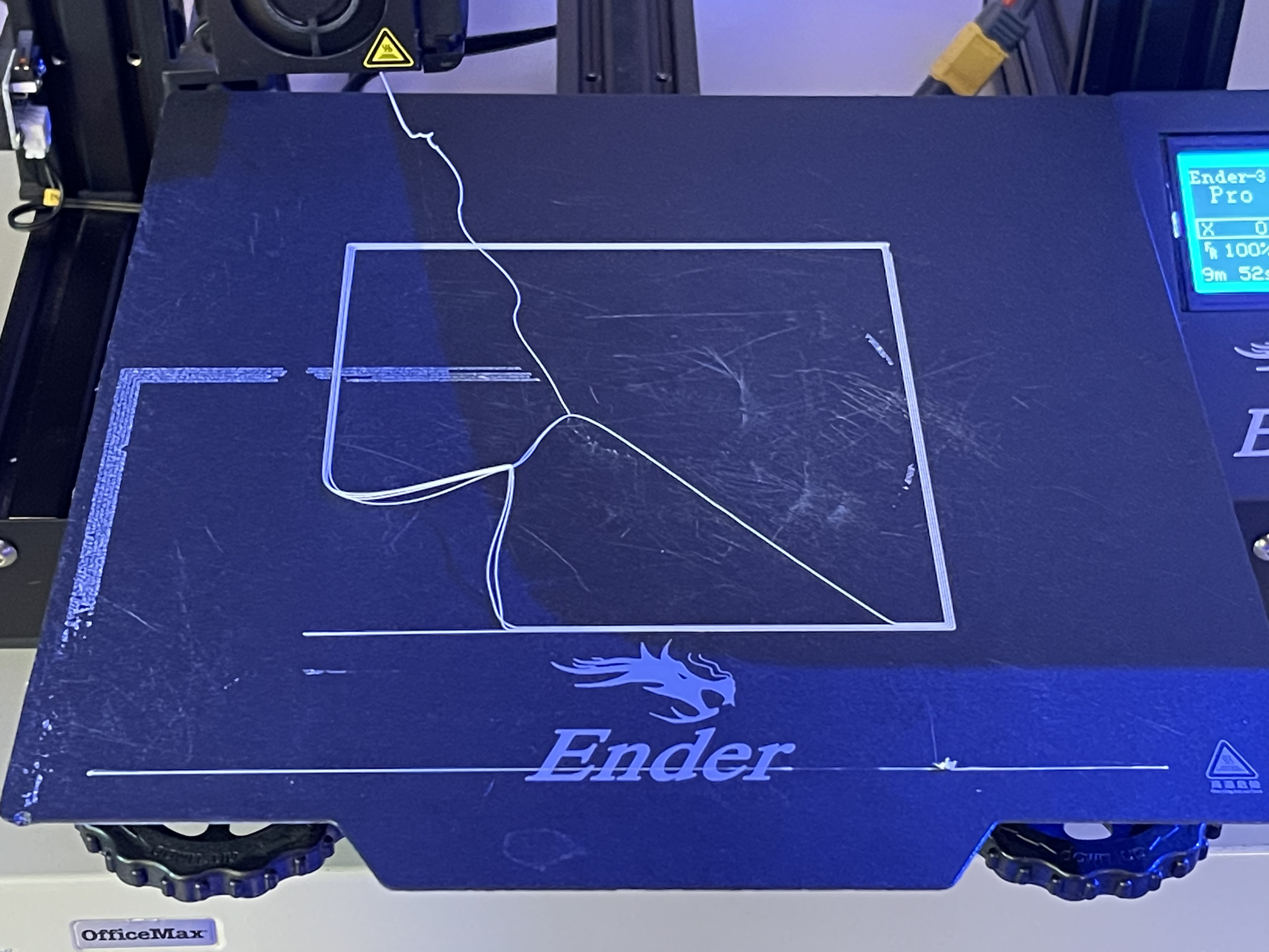
The algorithm I'm using relies heavily on distance calculations. If the distance is calculated incorrectly, as it was in the image above, it will over-extrude plastic. This mistake was actually key in helping me understand just how much plastic it's possible to extrude from the nozel and understanding what a wide range of extrusion values the nozzle has.
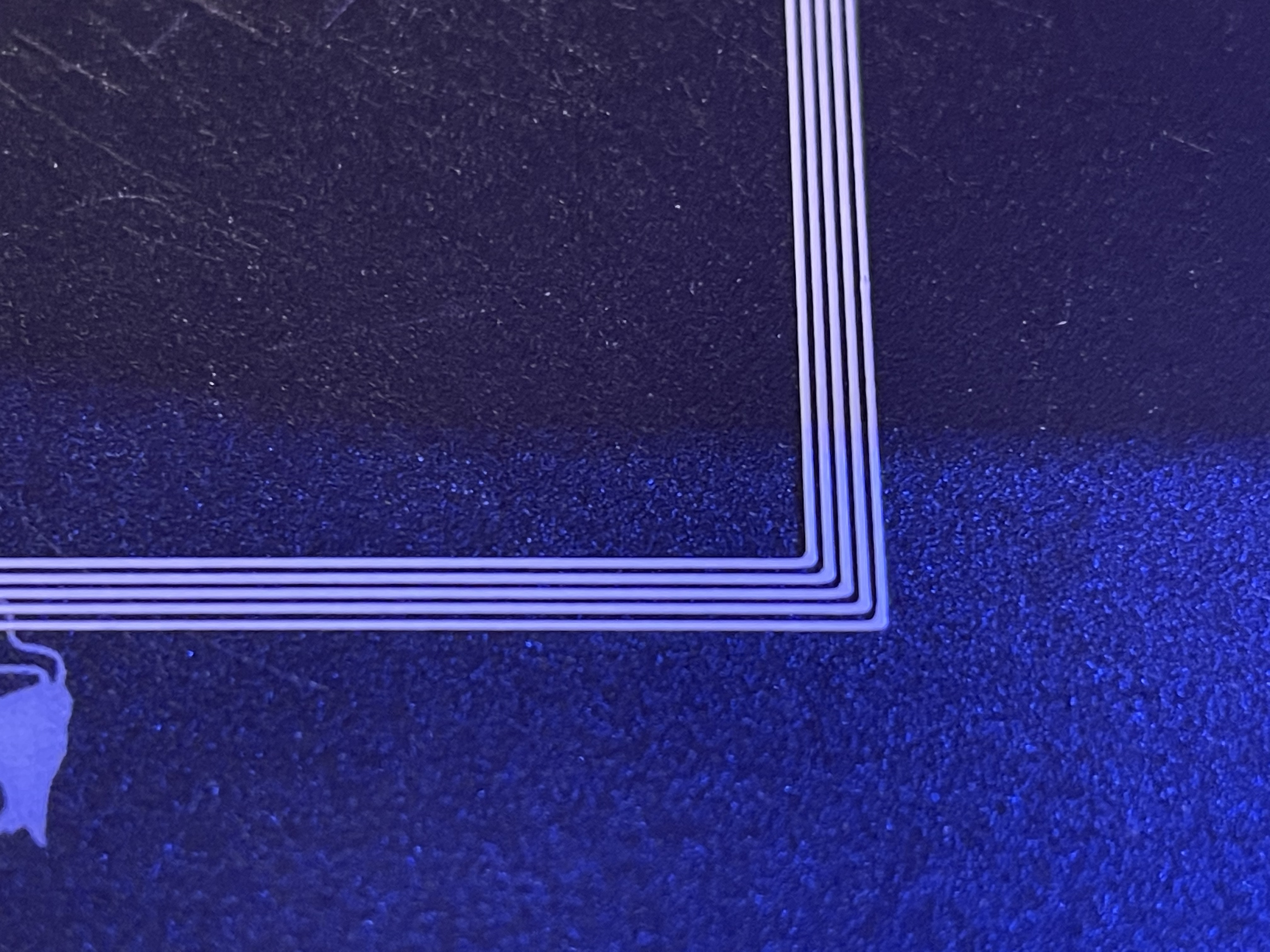
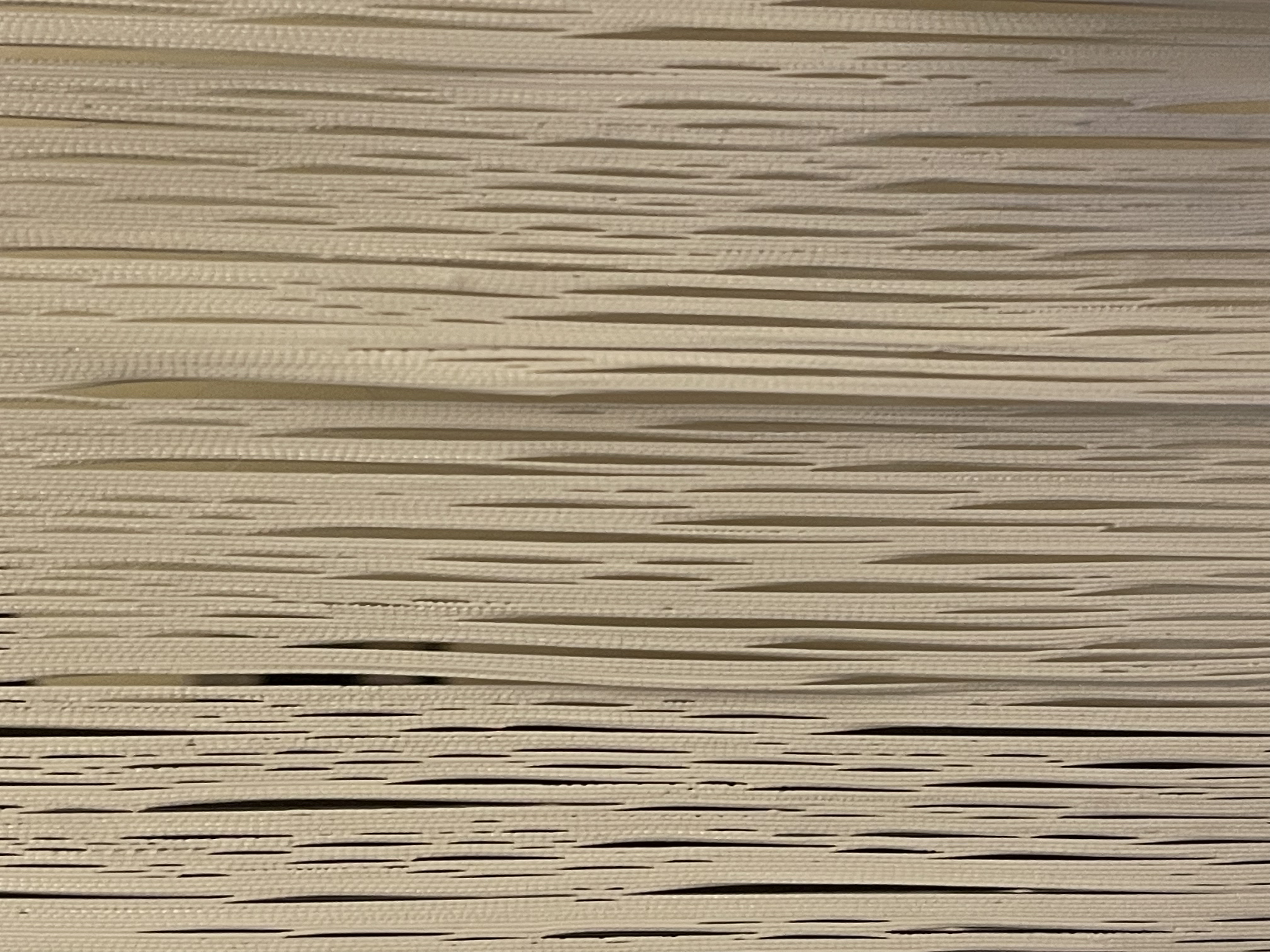
Closest I've come to actually achieving the kind of control I set out to create with my 3D printer was when I inadvertently created what feels very much like horsehair. From this image, it's clear that the warp and weft calculations I am making are making a difference in the texture of the plastic I'm extruding. It does not reveal an image and it's likely that the warp and weft are too dense for this plastic and nozzle diameter.
Though I did not try this pseudo-horsehair on my viola, I do believe it would have played music and it approximated hair quite closely. It was a surprise, but also indicated that my mapping was actually having an effect on the print, though not enough to see an image.
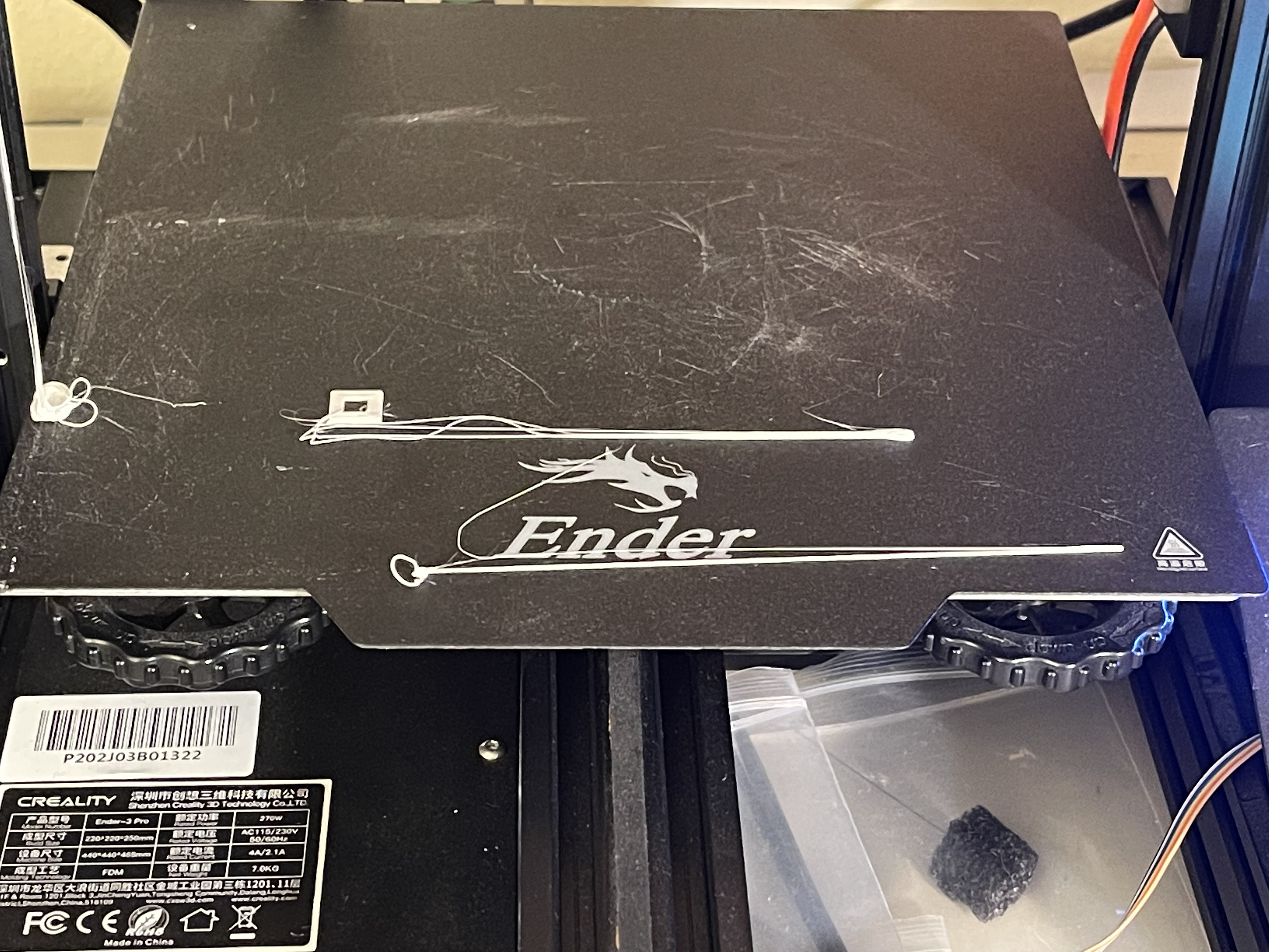
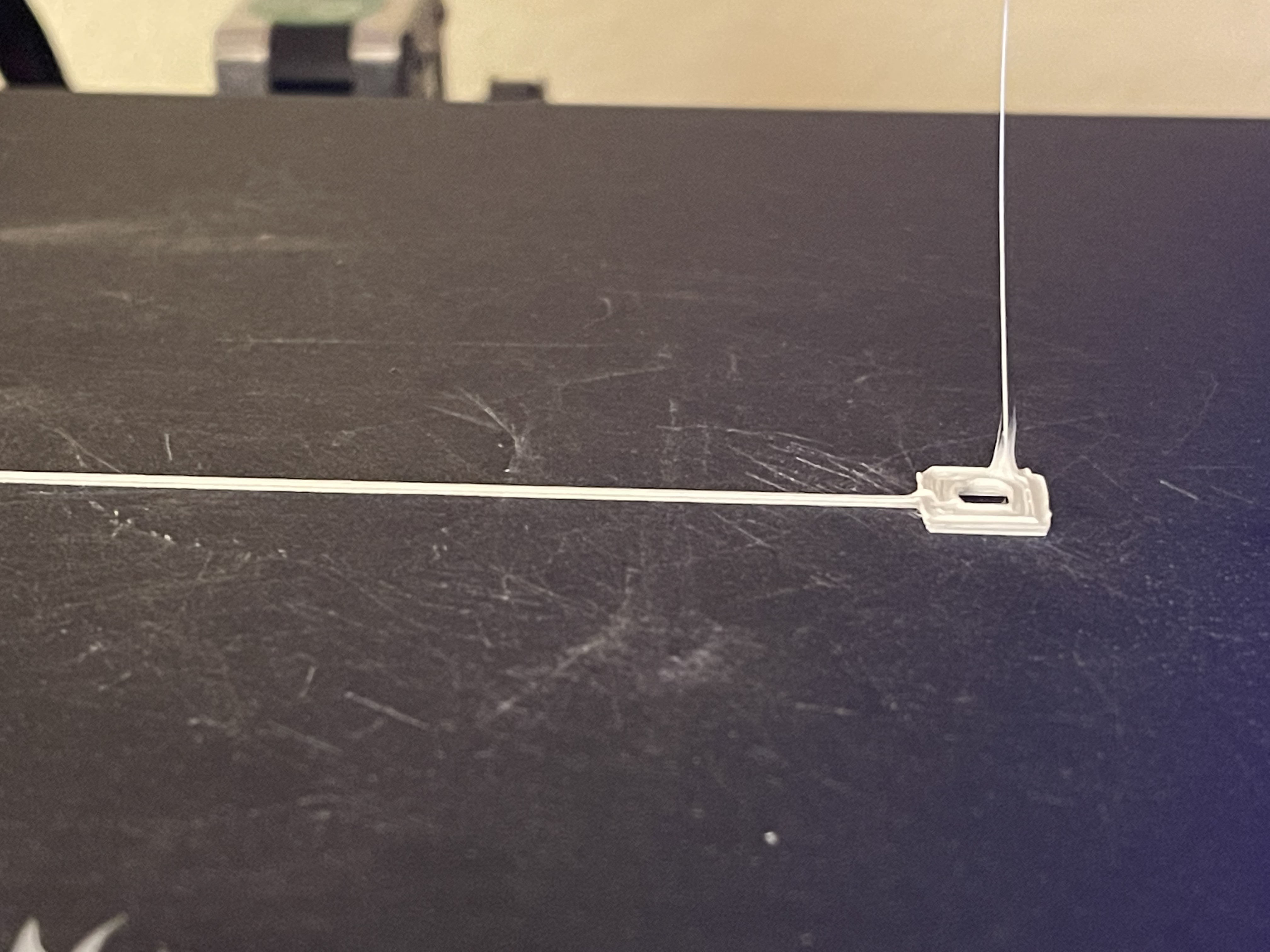
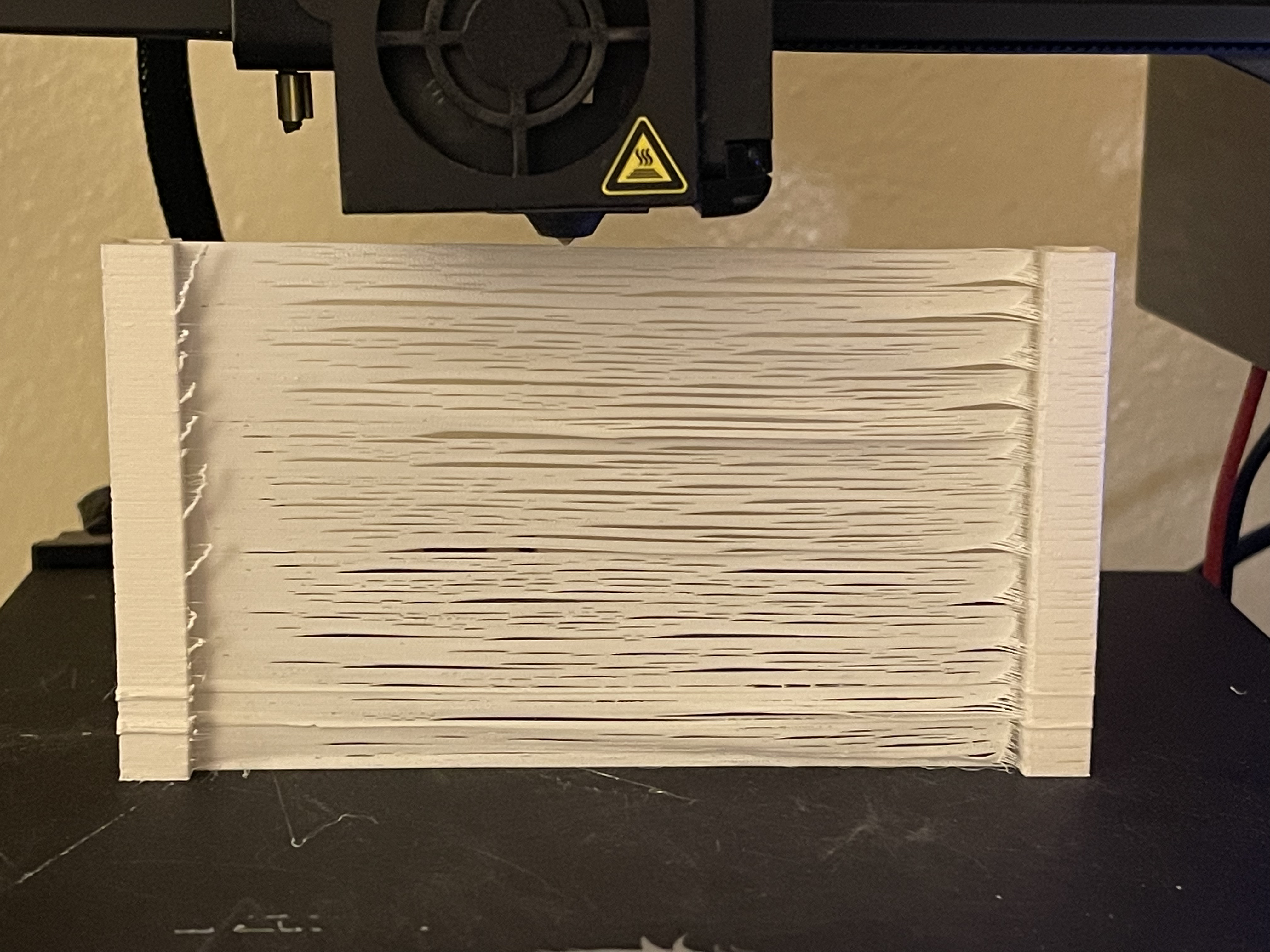
Eventually I was able to successfully print posts and a single layer of plastic. This is a zoomed out version of the horsehair image from the last section. As you can see there is a problem with adhesion of the layers, but the posts being successful is good incremental progress.
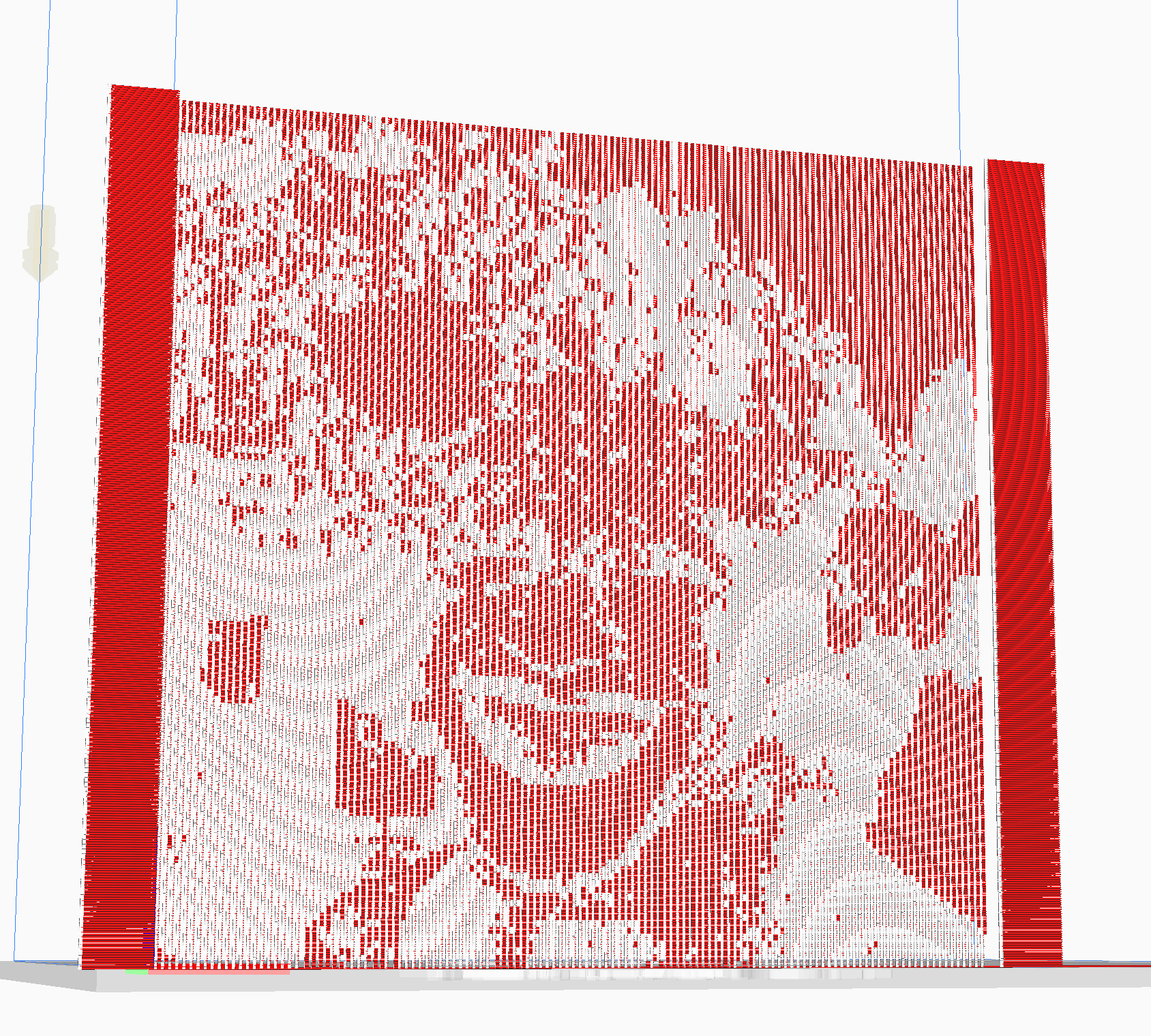
Ultimaker Cura afforded me the possibility of simulating extrusion and so I took advantage of the opportunity to illustrate the work I did on image processing and translating that to the Gcode. Although the image does not show up when printed, it does show up in Cura, so I believe it will be possible to print if I continue to adjust parameters.
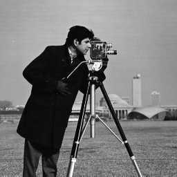
I used 3 images. The first is well-known and is called 'camera man.'
The processed image from Cura:
The next two images I used in honor of Pride month. The first is of transgender gay-liberation activist Marsha P. Johnson.
And the processed result:
The last image in honor of Pride month is of Harvey Milk, San Francisco's first gay mayor.
And the processed result:
Although I haven't been able to achieve a successful printed image, I do believe the foundation is set here for future success and building off of this codebase. The biggest takeaway from the project was getting hands-on experience with how minute and precise control of a 3D FDM printer can be with a customized Gcode parser.
It became clear to me when I produced the horsehair that the idea of a warp and weft of equal size was probably not going to result in a successful print with any kind of visual definition. That has gotten me to rethink the distances a bit. Here is one speculative plan for a new warp/weft template.
The equation takes time to change from one extrusion multiplier to another. Having a longer distance between the warps may allow time for there to be a discernable differene in the plastic's thickness. That increase in discernability may lead to an image being more visible.
3D printing a 128x128 pixel image that has a lot of gray in it as a test may not be the best test of this technology. The ideal approach in designing a system like this would be to print thin strips where portions of the image are totally black or totally white. Once those two shades are printing successfully, then I could move on to create strips with more shades of gray.
For this purpose I developed two test strips that I will use in future work:
In this process it became clear that I didn't understand the equation as well as I should and that extruding the right amount or using the right multiplier would require a deeper knowledge of the extrusion equation. In this image, I've graphed it and am manipulating the length of the span. You can see that the length of the span affects the slope of the extrusion.
This would mean that on spans that are mapped to the minExtrusion
variable would be less affected, but the maxExtrusion mapped spans
would be a lot denser. This increase in difference could be the key to
making the image visible.
- OpenCV
- Windows
- Linux
- Mac
This project uses the CMake to generate the development environment. In
order to get the project running your machine you need to install the CMake and download the project. You will also need to download and compile OpenCV. The way I've done it is I've downloaded it into a middleware folder and created an environment variable called OPENCV_DIRin my shell that points to the header files. The CMakeLists.txt file looks for that exact environment variable, so spell
it exactly the same.
After that, you need to create a build folder inside the project. Then you can build the project with the CMake. This has been testec on MacOS, but the CMakeLists.txt file and all libraries are cross-platform so it should work on Linux, MacOS, and Windows.
#MacOS commands
$ cd Image2Gcode
$ mkdir build
$ cd build
$ cmake ..
$ make
$ ./Image2Gcode
- Masood Kamandy (masood@masoodkamandy.com): Software Engineer and Researcher
This project wouldn't be possible without the mentorship and teaching of Jennifer Jacobs. I'm grateful for her support, the course she taught, and the original Python base code she provided for me to work with.
I'm also grateful for the helpful email correspondences I've had with Jack Forman and the work his team did at the MIT Media Lab for inspiring this investigation.
This project is available to license under a Mozilla copyleft license. Please see the license file for more information.
- Jack Forman, Mustafa Doga Dogan, Hamilton Forsythe, and Hiroshi Ishii. 2020. DefeXtiles: 3D Printing Quasi-Woven Fabric via Under-Extrusion. Proceedings of the 33rd Annual ACM Symposium on User Interface Software and Technology. Association for Computing Machinery, New York, NY, USA, 1222–1233. DOI:https://doi.org/10.1145/3379337.3415876
- Takahashi, H., & Kim, J. (2019). 3D Printed Fabric. Proceedings of the 32nd Annual ACM Symposium on User Interface Software and Technology. https://doi.org/10.1145/3332165.3347896
- OpenCV C++ Documentation. OpenCV. (n.d.). https://docs.opencv.org/master/d1/dfb/intro.html.
- MarlinFirmware. (2021, June 4). Gcode. Marlin Firmware. https://marlinfw.org/meta/gcode/.
© Copyright 2021 Masood Kamandy. All rights reserved. Last Updated June 10, 2021.
