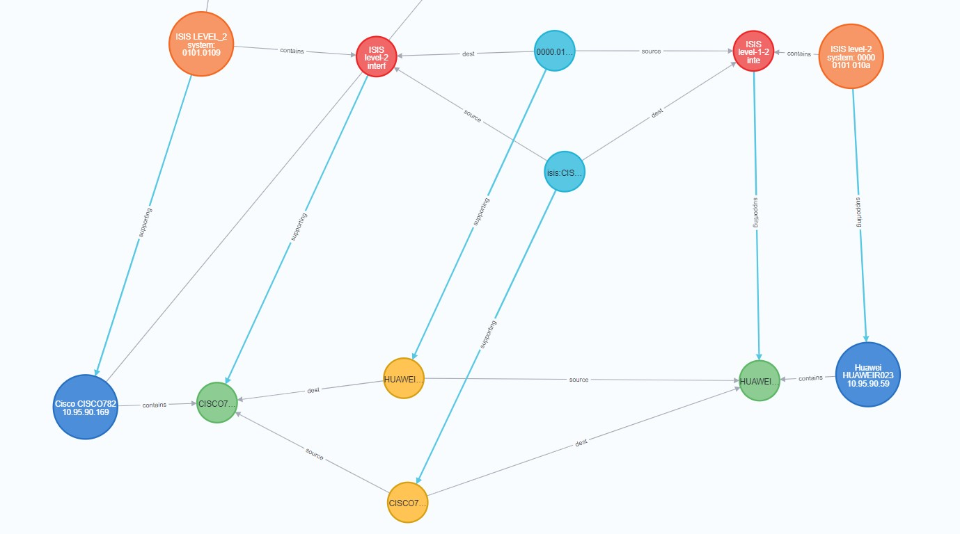
Digital maps are crucial tools that provide graphical representations of geographical data, enabling users to visualize and interact with spatial information effectively. As outlined in RFC 8345, which focuses on the architecture of network topology maps, digital maps can represent complex network topologies, offering insights into the relationships and interconnections between different network elements.
These maps enhance our understanding of both physical and logical structures, allowing for better planning, management, and troubleshooting of networks. By integrating various data sources, digital maps facilitate real-time updates and analytics, making them indispensable in fields such as telecommunications, urban planning, and logistics. The standardization of mapping protocols, as discussed in RFC 8345, ensures interoperability among different systems, further advancing the utility of digital maps in various applications.
The Core components are:
- Network Topology: Defines the structure and layout of the network, including nodes (devices) and links (connections).
- Node: Represents a network device, such as a router or switch. Each node can have attributes, such as its identifier and type.
- Link: Describes the connection between two nodes, detailing the characteristics like bandwidth and latency.
- Termination Points: These are specific endpoints of links within a network. They represent the interfaces where devices connect and facilitate data transmission. Each termination point is associated with a node and is crucial for defining how data flows across the network.
- Support Relationships: This refers to the associations between nodes and the networks they support. A supporting node may provide additional functionality or redundancy, indicating that one node relies on another for certain operations. These relationships help in understanding the dependencies and interactions within the network, enhancing overall topology representation.
Together, termination points and support relationships enrich the network topology by providing clarity on connectivity and operational dependencies, essential for effective network management and troubleshooting.
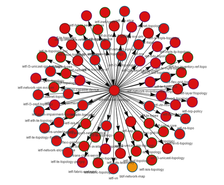
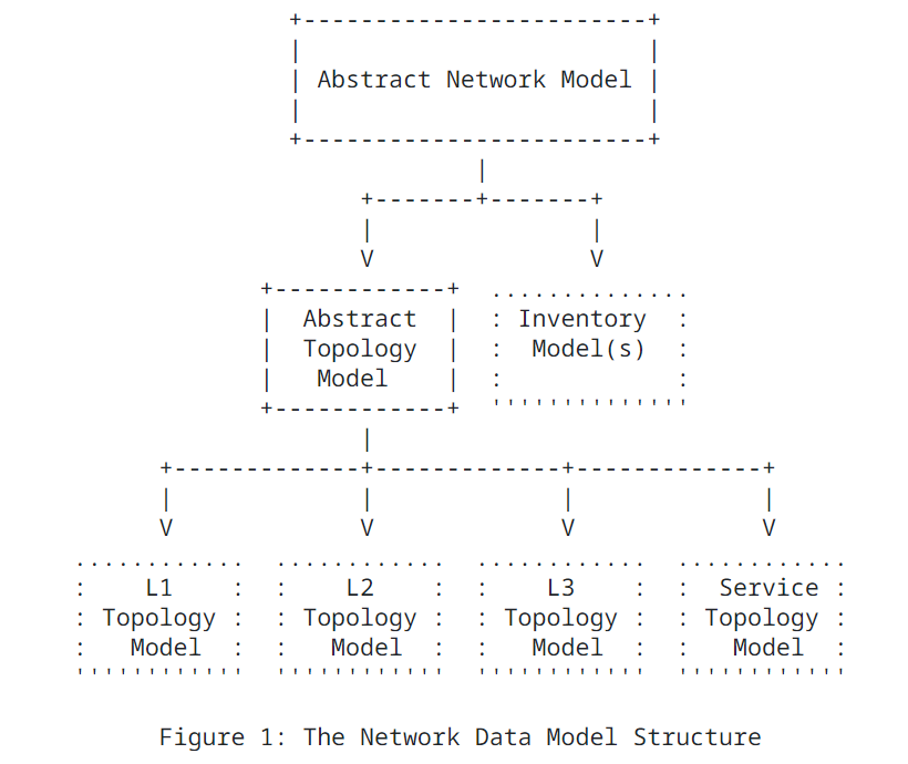
Below is a snippet from RFC8345. It shows the core modules and sample of other augmentations.
The abstract network node is augmented by inventory and
topology data models with inventory-specific and topology-specific
attributes. The network hierarchy (stack) allows any given network
to have one or more "supporting networks". The relationship between
the base network data model, the inventory data models, and the
topology data models is shown in Figure 1
As we see here there are ~76 rfc8345 augmentations. Each to model a certain layer/use-case.
Our intention here is to share to community how to use RFC8345 and some of its augmentations to model multi-layers in a real network.
In simple terms to model layers as networks , nodes, links and termination points. And to connect layers together using the supporting relationships.
In the demo we aim to:
- Map yang based topology modules to json ones.
- Collect device configs using netconf such as running-config, xpath of certain modules
- Map device level yang data to topology data.
- Create nodes in each layer with their respective termination points.
- In each layer, add links between termination points.
- Add support relationships between layers.
- Provide an example northbound API to execute queries.
In this demo, we focus on the below three layers.
- ietf-l2-topology using rfc8944
- ietf-l3-unicast-topology rfc8346
- ietf-l3-isis-topology draft-ogondio-nmop-isis-topology
pip install -r requirements.txt
Result relations are stored in neo4j. You can follow below instructions to install neo4j docker.
docker run \
--publish=7474:7474 --publish=7687:7687 \
--volume=/tmp/neo4j_dir:/data \
neo4j:5.20.0
User has two options for the config collection phase.
- First by running config collection from network devices. In this case direct reachability is needed with netconf enabled on devices.
- Provide copy of the routers configurations.
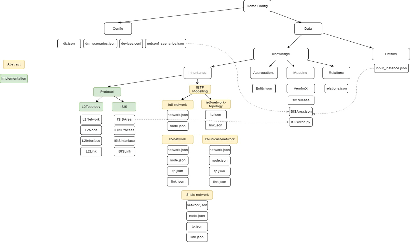
Under demos folder add your new folder demo name (in our example here it's "poc-simulated-demo")
- update with the neo4j ip and credentials
- Under the new demo folder, add netconf_devices which is a list of each device with vendor, device type, software version, IP address, port, username and password, device handler supported handlers.
In this section, we define what need to be collected from devices in order to complete the topology mapping for each layer.
- scenarios
- netconf_scenarios_configured specifies the netconf scenarios we want to run.
- It should always contain get_running_config for retrieving running configuration.
- server_capabilities retrieves the server capabilities
- get_yang_modules_summary retrieves the summary list what yang modules are supported by the device
- get_yang_modules retrieves all yang modules from the device
- get_yang_modules_and_submodules retries all yang modules and submodules from the device
- get_any_path retries the specific path defined with get_any_namespace, get_any_filter and get_any_file
- get_path_list retries the list of xpaths defined in entity_type_configured (list of entities) and xpath_configured (namespace and xpath)
- generate_flat_entity_types: Generates the concrete subservice types from parent abstract subservices (IETFLink, IETFNetwork, IETFNode and IETFTerminationPoint) and inheriting subservices.
- generate_dm_entities: Generates Digital Map entities or what we call subservices and stores to csv files. It retrieves the output of the generate_device_entities and generate_intent_entities and applies mapping to generate the Digital map entities.
- generate_dm_aggregated_entities: Generates Digital Map aggregated entities or what we can aggregated subservices and stores in csv files. These are network wide subservices that are not per device, like links, vpns, tunnels, etc. It retrieves the output of the generate_dm_entities and applies aggregation rules from data/knowledge/aggregation to generate the Digital map aggregated entities.
- generate_dm_relations: Generates Digital Map relations and stores in csv files. It retrieves the output of the generate_dm_entities and generate_dm_aggregated_entities and applies relations rules from data/knowledge/relations to generate the Digital map relations.
- generate_db_entities: Stores Digital Map entities from csv files (generated by generate_dm_entities and generate_aggregated_entities) to the Digital Map DB. It compares the content of files and current DB and only adds/modifies/removes for changes
- generate_db_relations: Stores Digital Map relations from csv files (generated by generate_dm_relations) to the Digital Map DB. It compares the content of files and current DB and only adds/removes for changes.
This part is used to add external entity instances at any layer. In our lab demo we added a new network called "Network:Demo LAB" in Network.json
{
    "Network":{
        "network-id":"Network:Demo LAB"
    }
}
In this section, we have the topology models at each layer mapped to json. Each layer is added with its properties and whether it has other parent model.
Here we define the base entities which are:
ietf-network/networkietf-network/nodeietf-network-topology/linkietf-network-topology/termination-point
These are the base models which will then be extended as shown in next sections.
Below is a snippet of network based on RFC8345.
The takeaway from this part is the importance of defining the key. key is used to uniquely
identify each network object in this example.
{
  "network": {
    "isAbstract":"yes",
    "key": ["network-id"],
    "properties":{
      "network-id":{
        "Description":"RFC8345 network-id: Identifies a network",
        "Type":""
      },
      "network-types":{
        "Description":"RFC8345 network-types. RFC8944 defines l2-topology for L2",
        "Type":""
      },
      "supporting-network": {
        "Description":"RFC8345 supporting network-id",
        "Type":"list"
      }
    }
  }
}
Defines the intermediate level abstract technologies at each layer which extends the
top base entities and also
can be extended as we'll see in next point. Below is a snippet of
IETF/ietf-l2-topology/l2-topology-network where you can see it's based on container:l2-topology-attributes
in rfc8944. Since we are define the
"l2-topology-network" we only look at the attributes under augmentation of
"/nw:networks/nw:network".
{
  "l2-topology-network": {
    "isAbstract":"yes",
    "parent":"network",
    "properties":{
      "l2-topology-attributes.name":{
        "Description":"Based on RFC8944 name: Name of the topology",
        "Type":""
      },
      "l2-topology-attributes.flags":{
        "Description":"Based on RFC8944 flags: Topology Flags",
        "Type":""
      }
    }
  }
}
This section is used as concrete implementations for the above definitions with more metadata if needed.
Below is a snippet of l2-topology/dm-l2-network where we extend IETF/ietf-l2-topology/l2-topology-network with
label.
It's worth to note that file name will be mapped at the end to the entity name. I,e l2 created entities at the end
will be named in our case dm-l2-network and so on.
{
    "dm-l2-network":{
        "layer":"l2-topology",
        "sublayer":"ethernet",
        "parent": "l2-topology-network",
        "properties": {
            "label": {
                "Description": "User friendly short label",
                "Type": ""
            }
        }
    }
}
If we take a snippet from entities_inheritance/IETF/ietf-l3-isis-topology/isis-topology-node.json you'll see
it's derived from draft-ogondio-nmop-isis-topology
{
  "isis-topology-node": {
    "isAbstract": "yes",
    "parent":"l3-unicast-topology-node",
    "properties": {
      "isis-node-attributes.system-id": {
        "Description": "System-id of the node.",
        "Type": ""
      },
      "isis-node-attributes.level": {
          "Description": "Level of an IS-IS node - can be level-1,level-2 or level-all.",
          "Type": ""
      },
      "isis-node-attributes.area-address": {
        "Description": "List of areas supported by the protocol instance",
        "Type": "list"
    }
  }
}
Here we generate the Digital map entities, each json file represent the entity type. Below is an example for generating "ISISArea".
Input_External_Files is amended to use device level extracted files (running-config, ietf-isis, etc)
Input_Internal_Files is amended if any of the previous entity files are needed to generate ISISArea entity.
Python_File is the one that has the mapping logic which basically takes internal/external files as input arguments, then
runs user defined logic to generate ISISAreas. For example, to generate network-id, network-types, area-address
and supporting-network-id.
{
  "ISISArea": {
    "Build_Mode": "netconf",
    "Build_Method": "python",
    "Input_External_Files": "openconfig-network-instance.json",
    "Input_Internal_Files": "Network.json",
    "Python_File": "ISISArea.py"
  }
}
Since this mapping might be different per vendor, OS, it's determined by the vendor + product + software version defined in the config for different controller types. For example: knowledge/mapping/cisco/ASR9K-X6/IOSXR781
This a crucial config where relations rules are defined. Relation rules defines the relation between:
- entities in the same layer (ex: ISISArea <> ISISProcess)
- entities between layer or as we say
supporting(ex: ISISArea <> Network)
Below is a snippet of adding a relation between ISISArea & ISISProcess. Here it's important that
we define the link between left entity primary key and right entity foreign key. In below example
rule is ISISArea.supporting-network-id Equal Network.network-id and relation type is supporting.
    {
        "src_entity": "ISISArea",
        "src_entity_attr": "supporting-network-id",
        "dst_entity": "Network",
        "dst_entity_attr": "network-id",
        "correlation_logic": "Equal",
        "type": "supporting",
        "properties": "",
        "show_name": "Supporting network for ISIS Area",
        "description": "RFC8345 supporting-network , network-ref"
    }
Relation logic can be more complex like below example (ISISLink <> dm-l2-link)
    {
        "src_entity": "ISISLink",
        "src_entity_attr": "source-ne-node & source.source-tp & dest-ne-node & destination.dest-tp",
        "dst_entity": "dm-l2-link",
        "dst_entity_attr": "source.source-node & source.source-tp & destination.dest-node & destination.dest-tp",
        "correlation_logic": "contained_in",
        "type": "supporting",
        "properties": "",
        "show_name": "Supporting interface for ISIS Interface",
        "description": "RFC8345 supporting-tp, tp-ref"
    }
The supported relation logics are Equal, contains, contained_in
When entity generation and relations are completed, output is stored in two places: results folder and neo4j
Here we get a csv file format for all the created entities and their respective relations
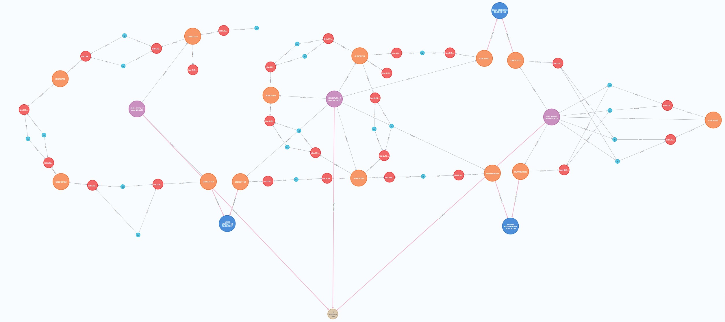
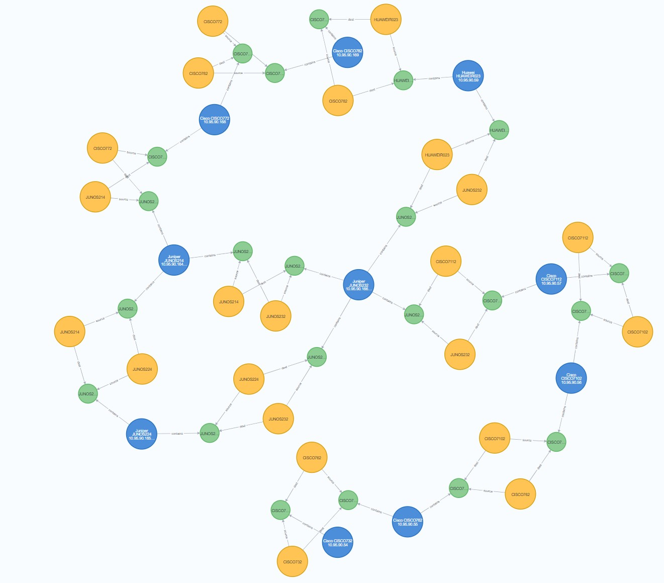
The generated entities and their respective relations are also stored in neo4j for more query interaction.
To get all ISIS neighbors, use below neo4j query
MATCH (srcne:ISISProcess)-[]-(source:ISISInterface)-[]-(link:ISISLink)-[]-(dest:ISISInterface)-[]-(dstne:ISISProcess) return srcne, source, link, dest, dstne
To get all L2 connectives
MATCH (srcne:`dm-l2-node`)-[]-(source:`dm-l2-interface`)-[]-(link:`dm-l2-link`)-[]-(dest:`dm-l2-interface`)-[]-(dstne:`dm-l2-node`) return srcne, source, link, dest, dstne
GET /discover-lab/demos/poc-simulated-demo will start reading the netconf_devices & netconf_scenarios to connect
to devices and retrieve the needed configurations. They will be then stored under generated/netconf directory.
GET /generate-dm/demos/poc-simulated-demo will run the steps defined in the digital_map_scenarios
section. Will store entities and relations in neo4j if needed as well.
GET /restconf/v1/data/ietf-network:networks/network is an IETF like API to retrieve all networks
Example response can be found in results/examples/mock-dm-ISIS-instance.json
