This repository contains firmware to reflash the motor controller that comes with hoverboards. The new firmware allows us to control the wheels by commanding the speed (in rpm, rotations per minute) for each wheel via UART.
- hoverboard motor controller board
- screwdriver
- solder / soldering iron / solder pump
- 4 male header pins
- 4-5 female to female jumper wires (5th one optional for reset pin)
- optional female to male jumper wire (and wire cutters) (for reset pin)
- ST Link V2
In the setup, we'll be referencing positions of certain things on the board. To make sure we're all on the same page, let's orient the board such that the longest side is at the top.
Before we can wire anything up, we'll need to prepare the board by soldering debug pins onto it, marked in red below:

- Unscrew all 12 screws on the perimeter of the board to remove the metal plate backing.
- Remove the solder from the debug pin holes (using the iron and the solder pump).
- Place the 4 male header pins into the debug pin holes.
- Solder the pins into place
- Screw the 12 screws back to put the metal plate back.
Time for the reset pin! Note that this is entirely optional. By doing the next few steps, it makes programming the device a lot more reliable. Otherwise, it may take a few tries to program the device successfully.
- (Optional) Cut a female to female jumper wire so that wire is as long as possible.
- (Optional) Taking the long piece, strip a tiny bit off the snipped part, and solder it into the far end of the resisitor attached to pin 7 (just to the right of the ST, marked in red above). It may be marked R15 or R19 depending on your hoverboard model.
To flash the ST, we'll need to connect the debug pins to our ST Link V2 microcontroller. The 4 pins to the left of the ST, from top to bottom, are:
SWDIO
GND
SWCLK
3.3V
Depending on what ST Link V2 you have, you'll hook it up differently. If you have the 10 pin version that plugs directly into the computer USB port, just match each of the debug pins to however your ST Link V2 is labeled:
| Motor Board | ST Link V2 |
|---|---|
| SWDIO | SWDIO |
| GND | GND |
| SWCLK | SWCLK |
| 3.3V | 3.3V |
| reset pin (optional) | RST |
If you have the 20 pin version, reference the following pinout:
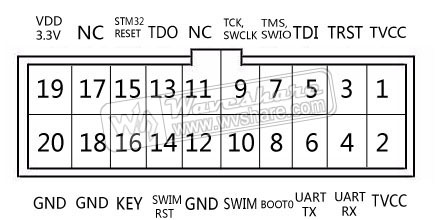
| Motor Board | ST Link V2 |
|---|---|
| SWDIO | SWDIO (Pin 7) |
| GND | GND (Pin 12, 18, or 20) |
| SWCLK | SWCLK (Pin 9) |
| 3.3V | 3.3V (Pin 2) (And connect Pin 1 to Pin 19*) |
| reset pin (optional) | RST (Pin 15) |
*We need to 1) power the ST and 2) let the ST Link know that the device is powered (TVCC). To do this, we use Pin 19's 3.3V to power both TVCC (Pin 1 & Pin 2) and the 3.3V pin on the motor board. Since Pins 1 and 2 are internally connected, connecting Pin 19 to either of them powers the other one, and we can connect the other one to the 3.3V pin on the motor board.
Now that everything is wired up, let's make sure we can communicate between our computer and the ST chip on the microcontroller. If you don't already have the ST-link tools, you can install it by following the instructions for your operating system on the README of the Stlink Tools Repo.
Following the installation guide:
$ sudo apt-get install cmake
$ sudo apt-get install libusb-1.0.0
$ git clone https://github.com/texane/stlink.git
$ cd stlink
$ make release
$ cd build/Release; sudo make install
$ sudo ldconfig
Now that you have the tools ready, let's probe our ST link to see what it's detecting:
$ st-info --probe
In response, we should see something like:
Found 1 stlink programmers
 serial: 563f7206513f52504832153f
openocd: "\x56\x3f\x72\x06\x51\x3f\x52\x50\x48\x32\x15\x3f"
  flash: 262144 (pagesize: 2048)
   sram: 65536
 chipid: 0x0414
  descr: F1 High-density device
If you have a device show up, we're ready to move on to the next section! Otherwise, feel free to check out some common problems:
- If you see:
Found 1 stlink programmers
This means that the ST Link is detected, but it can't find the ST. This usually means that the TVCC pin isn't getting 3.3V or the ST isn't getting 3.3V. Make sure your ground and power pins are hooked up correctly, as detailed in the previous section (ie, for the larger ST Link, pin 19 -- pin 1, and pin 2 -- ST 3.3V).
- If you see:
Found 0 stlink programmers
This generally means that your computer couldn't find the ST Link V2. Make sure your ST Link V2 is connected to your computer and wired up correctly. You can also try unplugging it and replugging it in. If it still is not detected, try restarting your computer to reset your serial ports. If that still does not work, you might have a borked ST Link V2, and you should acquire another one.
A lot of the STs come locked for protection. We can unlock it (which erases the code on it) using openocd (which is installed with ST Link Tools):
$ openocd -f interface/stlink-v2.cfg -f target/stm32f1x.cfg -c init -c "reset halt" -c "stm32f1x unlock 0" -c "reset halt" -c "exit"
In response, you should see a bunch of INFO messages, as well as:
stm32x unlocked.
at some point in the messages. If you see the unlocked message, we're ready to move on. If you can't unlock it, you might need to find a device with windows OS, and use the ST Link tools to unlock it.
Now that everything is set up, it's time to actually flash some new firmware onto the device!
In order to compile the firmware you'll need to install the GNU Embedded Toolchain for Arm. You can download and install the toolchain appropriate for your development machine or use your favorite package manager. Below are instructions for using homebrew on MacOS.
$ brew tap PX4/homebrew-px4
$ brew update
$ brew install gcc-arm-none-eabi
$ sudo add-apt-repository ppa:team-gcc-arm-embedded/ppa
$ sudo apt-get update
$ sudo apt-get install gcc-arm-embedded
$ sudo ln -s /usr/bin/arm-none-eabi-* /usr/local/bin/
Before we can flash the code that moves the motors, there are some values we need to configure. If you open up the config file, you'll see a bunch of things that can be configured. Right now, we just need to turn on calibration mode -- uncomment the line that defines CALIBRATION.
#define CALIBRATION //comment out when not in use
Now that that's set up, we can flash the calibration firmware by:
- cd-ing to your repo (the directory containg the inc/ and src/ directories and the Makefile).
- Compile the files by typing
$ make
- Flash our device!
$ st-flash write build/hoverboard.bin 0x8000000
If it works successfully, you'll get a message that ends with:
INFO src/common.c: Starting verification of write complete
INFO src/common.c: Flash written and verified! jolly good!
Note that if you haven't connected the reset pin, and get the following error, you may need to try it a few times.
INFO src/flash_loader.c: Successfully loaded flash loader in sram
  x/12 pages written
ERROR src/flash_loader.c: flash loader run error
ERROR src/common.c: stlink_flash_loader_run(0x8003000) failed! == -1
stlink_fwrite_flash() == -1
Before we turn everything on, in order to see what the ST is outputting, the UART pins need to set up. The three pins you need are located on the top right side of the board (right most 4 pin connector/harness), just next to the speaker. We'll be using the green (RX), blue (TX), and black (GND) pins - Note that the red pin is 14V and we do NOT want to use it. Hook the three pins to any device with 3.3V UART, and configure the UART to run at a baud rate of 9600. (Remember that TX (blue) on the board should go to RX of the other device and RX (green) on the board should go to TX of the other device). Please note that some boards have wire colors that do not match as described, so it is best to check. The order from left to right on the connector is GND, RX, TX, 14V.
If your device is a raspberry pi, make sure to enable serial in raspi-config and restart your pi. Then, you can use a program such as minicom. (You may need to apt-get install minicom first):
pi@raspberrypi:~ $minicom -b 9600 -D /dev/ttyS0
(Note that to exit out of minicom, you type Ctrl+A, then Q.)
Now that we have the UART set up, we can see what the configuration settings for the wheels should be. Turn on the motor board and wait for the wheels to slowly start moving - it can take a bit for the wheels to start moving. You should see messages of the format (which will repeat until turned off):
L+1:#
L-1:#
R+1:#
R-1:#
Now that we have the wheel offsets, we can finish the configuration file. Where it says WHEEL SETUP are a bunch of constants you need to fill in.
#define L_POS_OFFSET    5 // Number from L+1
#define L_NEG_OFFSET    2 // Number from L-1
#define L_WHEEL_DIR     1
#define R_POS_OFFSET    5 // Number from R+1
#define R_NEG_OFFSET    2 // Number from R-1
#define R_WHEEL_DIR     -1
Note that the positive and negative offsets should be off by 3 for either side - if it's not 3, try running the calibration mode setup longer, as it will occasionally be off by one.
The other constants in the config file should be set at this time as well. For a generic use case, these can be left with their default values.
- DEBUG mode - uncomment this if you want extra measurements over UART
- CONTROL_METHOD - should be either SINUSOIDAL or TRAPEZOIDAL
- WHEEL_HALL_COUNTS - should be 90 for hoverboard wheels
- MAX_POWER_PERCENT - the max power percent any wheel should reach
- POWER_CHECK_PERIOD - how often battery voltage and charging are checked
- TX_WAIT_PERIOD - how often to transmit measurements
- RX_WAIT_PERIOD - how often to process UART chars received
- HEARTBEAT_PERIOD - how often the board is expecting commands in ms (should be increased if manually typing commands to drive wheels)
Now that everything is set up, it's time to flash the board to move at our command!
- First, let's do some clean up because we've changed some of the values in our header files. If we recompile, we'll have the firmware we want to use.
$ make clean ; make
- Flash our device!
$ st-flash write build/hoverboard.bin 0x8000000
- Done! Feel free to turn it on by pressing the on/off button.
Now that the firmware is set up, it's time to command the wheels to move! The ST is expecting commands over UART at a baud rate of 9600. Since the UART communication implements a variation of SLIP, commands should be prefixed and postfixed with any of the newline characters: \r or \n or \r\n.
The command format is
L[rpm],R[rpm]
where rpm stands for rotations per minute, and is limited to the range ±12 to ±360.
More specifically,
L(-)##(#),R(-)##(#)
Some examples of appropriate commands are:
- L20,R20
- L12,R-36
- L-31,R-200
As a safety precaution, a heartbeat has been included (configurable in the config file). This means that the wheels will stop moving if it has not received any new commands in however many milliseconds specified in the config file.
If the status byte you are receiving back is not 0... that usually means something is wrong.
BAD_PARSING           0 (the latest SLIP frame format is wrong)
SPEED_OUT_OF_BOUNDS   1 (the rpm wasn't between ±12 and ±360)
HEARTBEAT_MISSING     2 (the most recent command is over x ms old)
MAX_POWER_REACHED     3 (the user max threshold has been reached)
LOW_BATTERY           4 (the battery voltage is less than 32V)
IS_CHARGING           5 (the battery is charging)
Note that the motor board will also start beeping when the voltage is too low.
Inspiration for the orginal version of this code can be attributed to NiklasFauth/Hoverboard-Board-Hack.
This project is licensed under the MIT License.