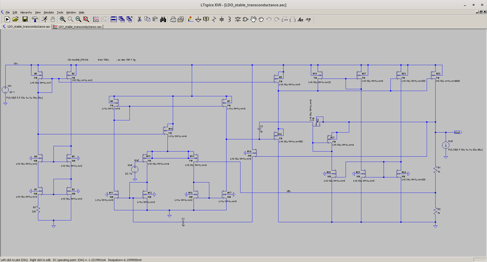
LDO
A simple LDO circuit capable of 3-Ampere output current, Iout
Output voltage, Vout could be determined or changed using Vref voltage source which is just a simplification of bandgap circuit.
Note;
- AC analysis Measurements are done using output load capacitance Cout of 10uF
- Both line and load regulation are tested without any output load capacitance Cout
Power Dissipation : 6.1 mW
Gain: 70 dB
Unity-Gain Bandwidth: 39.7 kHz
Phase Margin: 69.1 degrees
PSRR : 65 dB
load regulation : maximum 500mV change in Vout during sudden change (1us rise or fall time) of load current (from Iout=3A to Iout=0A, and vice-versa)
line regulation : maximum 8mV change in Vout during sudden change (1us rise or fall time) of input voltage (from Vin=5V to Vin=5.5V, and vice-versa)
TODO:
- Improve the phase margin of the LDO when there is no Cout (for acting as dominant pole)
- Improve load regulation metric result
Circuit Mechanism Explanation:
- Transient performance enhancement circuit consisting of M19, M27, M23, M24 and M25 work by passing extra biasing current through M18
- M14 acts as active miller compensation together with C1. M21, M22 and C2 act as dynamic miller compensation circuit.
Credit: Reddit forum
