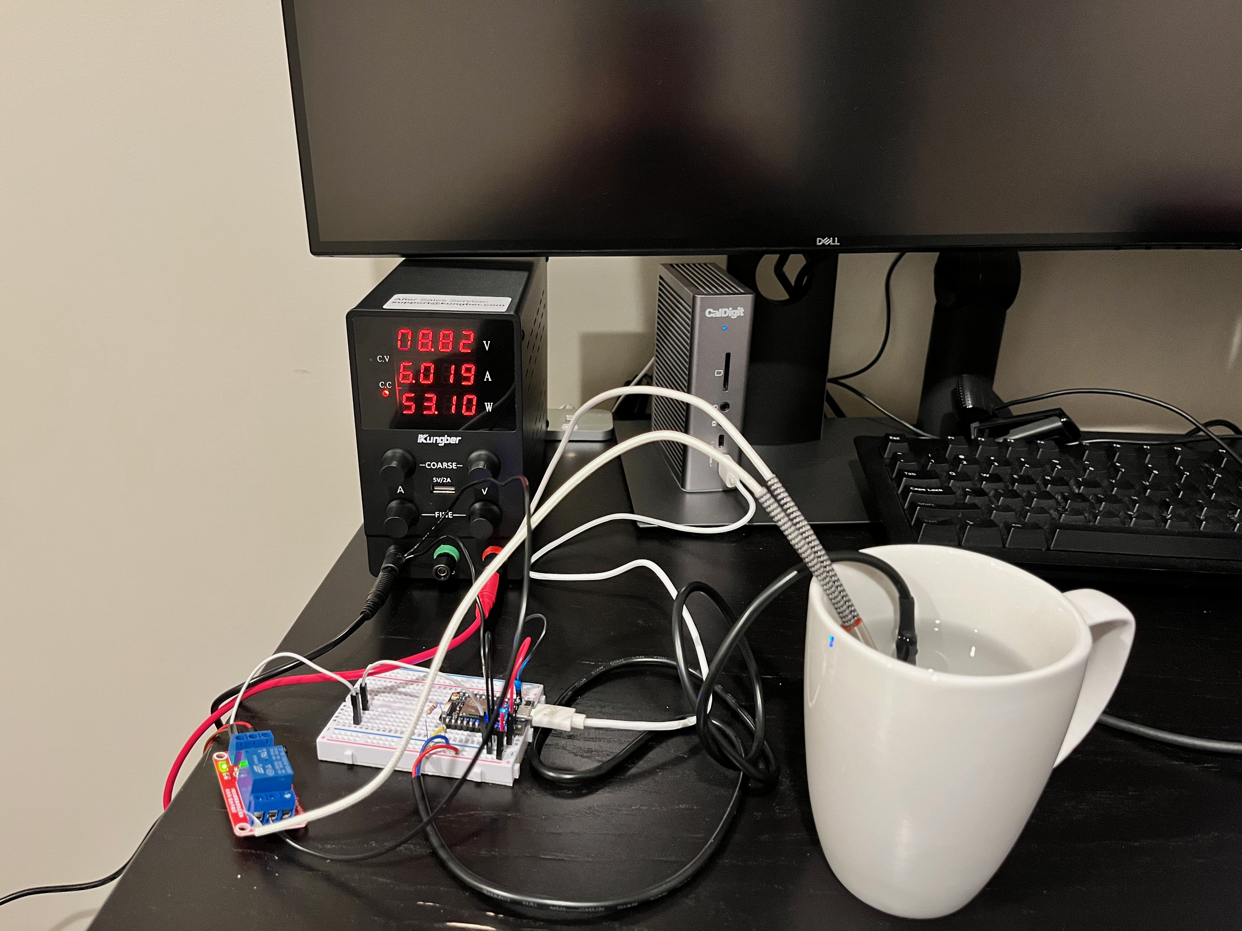
Why spend $100 on something when you can spend more and learn things?
A DIY version of the Ember Mug for nerds. We use a cartridge heater placed inside the mug to heat it along with a temperature sensor that monitors the temperature of the liquid in the mug. The cartridge heater is connected to a bench power supply and switched through a relay.
This project requires a cartridge heater that may draw 8A of current. Using this component without the appropriate safety precautions can result in serious injury or death. Please do not try this without understanding the dangers of working with high power components.
This project was done as a hobby. No guarantees are made about the quality of the instructions, design, or software provided. Please be careful.
| Component | Schematic Label | Documentation | Purchase Link |
|---|---|---|---|
| Particle Photon | U1 | Particle Docs | https://store.particle.io/collections/wifi/products/photon |
| DS18B20 Temperature Sensor | DS1 | Datasheet | https://www.adafruit.com/product/381 |
| SRD-5VDC-SL-C Relay | K1 | Datasheet | https://www.amazon.com/dp/B00LW15A4W |
| Dernord 12V 100W Cartridge Heater | R1 | Not Available | https://www.amazon.com/dp/B0741664G5 |
| Bench Power Supply | Not Available | https://www.amazon.com/dp/B08DJ1FDXV | |
| 4.7KΩ Pullup Resistor | R2 | Not Available | Widely Available |
This schematic diagram was made with Fritzing.
Note that the connection from D7 to the input connection on the relay is not shown. This is due to limitations on the
imported part file for the relay. D7 was chosen so that the on-board LED could be used to indicate the desire state
of the relay.
The cartridge heater is depicted as a 1.5Ω resistor calculated in the following way using the component's power and voltage characteristics:
P = VI # Ohm's Law
R = V / I
I = P / V
I = 100W / 12V
I ~ 8.3A
R = V / I # Ohm's Law
R = 12V / 8.3A
R ~ 1.5 Ω
This breadboard diagram was made with Fritzing.
Note that connections from the bench power supply are not shown. This is due to limitations in the Fritzing tool.
- The positive terminal should be connected to the red wire on the cartridge heater and the positive terminal of the relay coil.
- The negative terminal should be connected to the
GNDpin of the Photon. Since the relay coil's only reference voltage is the bench power supply, failure to make this connection will result in insufficent voltage across the relay input. This will prevent the relay from switching even when the input is driven high from the Photon.
This project uses a Particle Photon as the "brains" of the operation. If you're new to the Particle platform, head over to the quickstart to get your device up and running.
This project uses the Particle CLI for the development workflow. Hit their guide to get that setup and use the reference for any questions regarding that tool.
Once your device is set up and connected to your computer over USB, obtain your device name:
particle identifyThen check what port your device is on. If you're on a Unix system you can use:
/dev/tty.usbmodem1101Replace the values in /scripts/.env with your own. Then you can flash your device.
./scripts/flash.shFinally to listen to messages logged to the serial port, you can use this script:
./scripts/listen.shThe provided software is very simple. After some initialization, itt repeats this series of steps in a loop:
- Get current temperature from the temperature sensor
- Switch the relay by comparing the current temperature to the desired temperature
The DS18B20 temperature sensor uses the 1-Wire communication protocol.
This project uses the OneWire Community Library to manage
this communication. All we have to do is call two library functions. We call read to check if a new value is
available - the sensor only reads new values once per second by default. Then we call fahrenheit to get the latest
temperature reading in fahrenheit units.
We utilize a PID controller to drive the relay based on the error between the current and desired temperature. A PID controller is probably overkill for project like this, but it's used here for the purpose of demonstration and to achieve a higher degree of control than less sophisticated methods like a simple if statement.
This project uses a PID community library instead of implementing our own. This awesome blog post explains some of the advanced features of this PID controller.
Even with a good PID controller, we are somewhat hamstrung in our control of the temperature for two reasons:
- We are driving a digital output with no granularity. The relay is either open or closed. This is in contrast to other types of outputs such as a car motor to which we can apply differing degrees of thrust.
- We can only control the output in one direction. We can only apply heat to increase the temperature, but we have no way to actively cool the liquid in the mug. In a car, for example, we might have a brake available to us to slow the speed of the care when it exceeds the desired setpoint. This project assumes we are heating liquids to temperatures above room temperature so we can rely on natural heat dissapation to cool the liquid. However the liquid cools down slowly.
In practice, this project is able to control the temperature to within 2 degrees of the target temperature without playing with the PID gains too much. This could probably be improved, but we'll take it!


