I3C Blaster is a firmware image you can flash to your Raspberry PI PICO board to let it act as USB to I3C converter. Simply add 2 pullup resistors and you are ready to go.
I3CBlaster has 3 usage schemes:
- Interactive using a terminal program like Tera-term or Putty
- From a Python program running on PC
To automate any tests, or building your own GUIs, ... A powerful feature here is, that it has an autoidentification scheme to detect the COM port number automatically. No need to struggle with which of your 20 COM ports is from the I3CBlaster device 😃 - Need I3C in your on RP2040 C projects? Also possible, just integrate the i3c_hl module and you are good to go!
Although I have already a HDR-DDR mode implementation running it is not yet fully tested and so far SDR mode (12.5MBit/s) and the mandatory open drain is supported.
Have a look at my I3C daughter project, which is a Saleae Logic Analyzer plugin to decode I3C OD, I3C SDR and I3C HDR-DDR transfers: https://github.com/xyphro/XyphroLabs-I3C-Saleae-Protocol-Analyzer
It is an I3C controller driver code based on a single RP2040 PIO. Feel free to reuse it in other projects! The i3c_hl.c or .h files provide an interface to all kind of different I3C transfer types.
To include it in your projects as a module, simply use i3c_hl.h i3c_hl.c and i3c.pio. i3c_hl.h exposes all the i3c API functions for the i3c driver. But don't forget credits - this project took lots of late night work to make it work well :-)
Because so far there is no easy and low $ solution available to learn I3C protocol or evaluate I3C target devices in the market. Having the ability to execute I3C transfers was for me also a major step in understanding the I3C protocol and its many exceptions and hidden features and the reasons behind them.
I3C is a successor protocol based on I2C, but enabling higher transfer rates. It pulled in many mechanisms from the less well known i2c speed modes 3.4MHz (HS), 5 MHz or 10 MHZ. There are multiple transfer modes defined using SDR push-pull mode transfers, 2 different kinds of DDR modes are part of the public BASIC I3C specification. The full I3C specification even has multi lane support included enabling transfer rates over 100MBit/s and 2 flavors of called ternary modes where also the clock line is used to transfer data.
It maintains in a limited way compatibility to the I2C protocol. This legacy support simplifies the learning curve for new users, but creates complexity in the overall protocol definition.
Clock stretching devices, Multi master arbitration are not supported, a maximum of about 5 I2C devices on a single bus segment are the most dominant limitations for i2c usage on i3c busses.
It is also feasible to connect i2c and i3c devices on the same bus with limitations on max. capacitive load (50pF / 100pF) or max. datarate. Similar to i2c a degradation of the i2c clock frequency to cope with higher capacitive load is possible as function of drive strength.
Another very useful feature of I3C is the realization of the so called IBI feature: In-Band-Interrupts. I3C target devices have now the capability to raise an interrupt over the same 2 wires where it communicates with. There are 2 schemes implemented - one when the bus is busy and arbitration based scheme and another one when the bus is idle. The IBI features is easy to understand from bus perspective, but can cause a bit of headaches for SW stacks due to out-of context occurrence within the same communication channel.
Note that according to I3C protocol definition the IBI feature only works in SDR transfer mode, so whenever HDR modes are used and an IBI feature is required ensure to transition after transfers back to SDR mode with an HDR Exit condition.
Some resources:
| Name | Link |
|---|---|
| Public I3C Basic spec | https://www.mipi.org/mipi-i3c-basic-download |
| A good tutorial | https://community.nxp.com/pwmxy87654/attachments/pwmxy87654/tech-days/256/1/AMF-DES-T2686.pdf |
Quite easy, follow these steps:
Check your drawers, old projects or simply order one these $4 boards :-)
Enter the bin folder and download the I3CBlaster.uf2 file
- Ensure the USB cable is not connected.
- Press and hold the BOOTSEL button on the Raspberry PI Pico board.
- Then connect the USB cable to your PC.
- Now you can release the BOOTSEL button
- A flash drive should have appeard on your PC. Drag and drop the previously downloaded I3CBlaster.uf2 file on this drive. This will start the programming. Once done, the FLASH drive removed automatically and the firmware is READY TO USE. Congrats! :-)
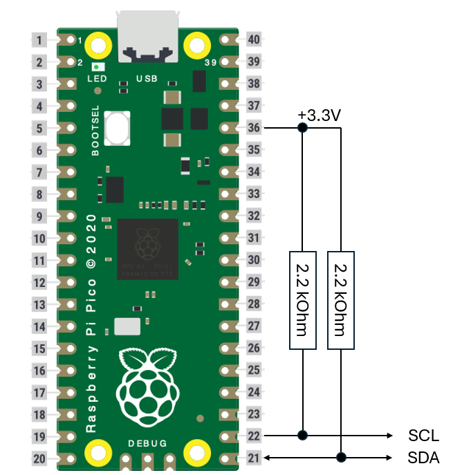
Connect 2 pullup resistors from the +3.3V pin of the board to GPIO16 and GPIO17.
As reference: I use 2.2kOhm resistors as pullups. Other values are possible too as function of your bus capacitance and speed.
GPIO16 is the SDA line. GPIO17 is the SCL line.
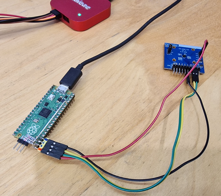
Connect an external I3C target to those lines + GND and supply.
Note, that the I3C bus operates on 3.3V IO levels. In case you want smaller IO levels you can use a device like LSF0102 or NCA9306 to translate to smaller levels.
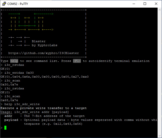
When I3CBlaster is connected to the PC you see a COM / TTY port, simply connect to it using Putty or Tera-term. The exact baud-rate parameter/encoding settings don't matter, because this is a virtual com port. After connecting a welcome message is shown. Press once the F1 key to help the command line interface identify the terminal emulation method. Without this e.g. the del/backspace key might behave unexpected.
Tab auto completion is supported - you can do in-line edits in your command, etc. Just like in e.g. an SSH session or command line interface.
Note that I3C Blaster supports the default Putty and Tera-term terminal emulations. It is not tested with other terminal programs and features like the in-line editing might go wrong.
Example Putty settings:

| Command name | Description |
|---|---|
| help | List all commands or give details about a specific command. You can just enter help or e.g. help i3c_clk to get information about a command |
| gpio_write | Sets a gpio pin state and direction |
| gpio_read | get gpio state. If no parameter is given a 32 Bit number containint all GPIO states is returned |
| info | Show some information about this version |
| i3c_targetreset | Execute a targetreset sequence on I3C Bus |
| i3c_clk | Set I3C clock frequency |
| i3c_scan | Scan for available I3C devices on the bus |
| i3c_entdaa | Execute i3c entdaa procedure. The I3C address to assign can be given as a parameter |
| i3c_rstdaa | Execute a I3C RSTDAA CCC broadcast transfer. This will un-assign all targets dynamic addresses |
| i3c_sdr_write | Execute a private write transfer to a target |
| i3c_sdr_read | Execute a private read from a target |
| i3c_sdr_writeread | Execute a private combined write read transfer from a target. Useful e.g. to read register values |
| i3c_sdr_ccc_bc_write | Execute a ccc broadcast write transfer |
| i3c_sdr_ccc_direct_write | Execute a ccc direct write transfer |
| i3c_sdr_ccc_direct_read | Execute a ccc direct read transfer |
| i3c_poll | Allows a readout of IBI or HJ (hotjoin) information from the bus. Call this function in case an IBI was signalled back when calling a transfer function or in regular intervals to ensure you get to see IBIs |
Each command parameters can be seen when typing:
help [functionname]
so e.g. help i3c_sdr_write
in the console
Each I3C command returns a single line response returning an error code and optionally data.
> i3c_entdaa 0x30
OK(0),0x04,0x6a,0x00,0x00,0x00,0x00,0x27,0xa0
OK(0) is the error code. There is always a text followed by a error number in brackets. 0 means: no error. The rest of the response shown above is data received during the entdaa process (e.g. BCR)
Reset any previously assigned dynamic address assignment:
> i3c_rstdaa
OK(0)
Now assign a dynamic address 0x30 to a connected i3c devices:
OK(0),0x04,0x6a,0x00,0x00,0x00,0x00,0x27,0xa0
Now scan the i3c bus for available i3c addresses:
> i3c_scan
OK(0),0x30,0x7e
As we can see the device is detected on address 0x30 and also the broadcast address 0x7E.
Now we can execute a transfer: In this case we write 2 bytes to the i3c device: 0x00 and 0x00 followed by a request to read 8 bytes.
> i3c_sdr_writeread 0x30 0x00,0x00 8
OK(0),0x00,0x01
The transfer was successful ("OK(0)") and 2 bytes were read. This is, because the device stopped the transfer after 2 bytes of reading. So also this is correctly handled by the I3cBlaster.
To be able to talk with I3CBlaster from Python I created a Python module.
This enables YOU to create automated testcases or even create GUI applications to use I3CBlaster with it.
The Python mode uses the same command line interface, but enables a special operation mode in it by starting each command with a '@' letter. This letter turns off the ECHO done by the command line interface when entering commands to get a bit more efficiency.
This module is done with the intention to be EASY useable. This e.g. involves also that I don't want you to struggle finding the right COM/TTY port number -> The COM port is identified automatically. Disclaimer: I did only test this under Windows, but it should work flawless under Linux too. Have to test this during next days once on my linux machine, but since a few weeks I am in a Windows mode (Yes, shame on me!).
The python module but also an example code is located in the python subdirectory. It should be pretty self explaining and exposes the same commands as the interactive mode.
The file i3cblaster_demo_runme.py is a python code using the i3cblaster module. i3cblaster.py contains the code of the i3cblaster module itself.
But to show how easy it is to use the API and entertain your curiosity quickly, here an example code:
import i3cblaster

# list available and connected i3c blaster devices:
devices = i3cblaster.listdevices() # this returns an array with serial numbers of connected i3cblaster devices
print(len(devices), ' i3cblaster devices connected:', devices)

if len(devices) > 0:
    i3c = i3cblaster.i3cblaster() # in case multiple devices are connected you can provide the serial number here as a parameter

    print('resetting dynamic addresses previously assigned')
    i3c.i3c_rstdaa()

    print('scanning for available i3c devices')
    targets = i3c.i3c_scan()
    print('found target devices on bus:', targets)

    print('assign a dynamic address - this only works for i3c devices supporting it, but will not cause issues')
    i3c.i3c_entdaa(0x30)

    print('scanning for available i3c devices')
    targets = i3c.i3c_scan()
    print('found target devices on bus:', targets)


    print('reading up to 10 bytes from subregister 0x00:')
    data = i3c.i3c_sdr_writeread(0x30, [0x00], 10)
print('result: ', data)The i3c_hl implementation using PIO is supporting the i3c address phase arbitration scheme.
A transfer will always start with an arbitration header written in Open Drain mode. This is the only flexible method which supports all I3C environments. Why? Think about a device wants to raise an IBI and does that at a point of time where a private read to the same I3C device is executed: The controller is not capable to differentiate in that case between if an IBI with payload was received or the actual read data. For limited well known environments I3C allows also tweaked performance optimized addressing phases, but here I did not support them for the reason of flexibility.
Although you see 2 pullup resistors have to be added, the lines get driven in push-pull mode during SDR phases. I3C does not require a pullup on the SCL line as it is driven by the master in push-pull mode, still I add here one. Why? Because I2C functions will get added to this too soon and I2C requires a pullup resistor.
Something very important to know on I3C protocol is that the ACK phase is different to I2C ACK. On I2C only the state of the line during HIGH phase is used for acknowledgment information. On I3C the ACK - although it looks very similar does signal if "more bytes can be transferred" and the Controller can signal also back if it want to continue transfering more data bytes.
Pull requests are very welcome!
What about e.g. making a Micropython module out of it? this would add a lot of value and I'd love to see that coming.
(Update 3rd November 2024: I started looking into it and it seems very feasible to create a .MPY module which can be imported like a normal python module. The difficulty lies into combining the MakeFile based system with the CMAKE based PICO SDK build. This will also likely be the case we don't see that many .MPY modules for RP2040. A bit more complex Frankenstein approach has to be me made... But I'll look into it further).
Feedback very welcome -> See discussion section or for problems: File a ticket in issues section!
But note: I won't be able to respond always immediately, ... Sometimes it can be within hours, sometimes days or months. I don't make a living out of this and simply want to increase the amount of i3c tools available to the public. Consider this a community project and try to help yourself also - the full source code is included in this repository.
The project is setup to work without pico SDK being installed. You only need to have a VSCode installation with arm-none-eabi toolchain and CMAKE. After configuring CMAKE you the picosdk is downloaded during first build. After any further builds the presence of picosdk is detected and no further buildtime gets wasted.
In case you reuse, please give visible credits according to the MIT license.
So: Have fun using it!
Disclaimer: Use at your own risk. I am not guilty for any negative effect like broken hardware or dataloss. Also: No animals were harmed during creation of this. I3C is a trademark of MIPI Aliance, MIPI is a trademark of MIPI Aliance. This development is done by an individual contributor and not done by or related to MIPI Aliance.
In case MIPI Aliance is not OK that I use the I3C term here contact me under "xyphro at gmail.com" and I rename it to something else following what has been done with I2C for many years resulting in "style flower analogously" like TWI (two wire interface) or others.