PicoMax
A basic voltage glitcher built around the Raspberry Pi Pico and a MAX4619 switch IC.
Building
If running on Arch install pico-sdk and logout-login for the environment
variables to be set.
cd src
mkdir build
cd build
cmake ..
make
After a successful build, you'll have the picomax.uf2 file in the build
directory that can be flashed:
picotool load -F picomax.uf2 && picotool rebootGlitcher commands
I have tried to reduce the amount of commands necessary for an explorative
sweep to just one atomic command, but it didn't yield any actual speedup
compared to the separate W, D and G commands.
Note for GCC13
Ensure this PR is merged: raspberrypi/pico-sdk#1367
Glitching
The glitcher is to be controlled with the src/controller.py script.
Delay and width calculation
The delay and width are in Raspberry Pi Pico clock cycles. The Pico runs at 125MHz (save ring oscillator variability), thus delays can be varied by 8ns increments.
With my specific MAX4619, switching time is
Same applies for the glitch width.
Given the above timings, it is more effective to switch between 5V and some intermediate voltage that will not instantly trigger the brownout detector of your target, but still achieve a succesful glitch.
Succesful glitching setup
I have managed to glitch the program in target_src running on a PIC16LF1936
with the following setup:
power supply: 3.3V
glitch voltage: 1.40V
glitch delay: ~235 cycles
glitch width: ~35 cycles
Previously, I had managed to glitch a loop opearting on variables in registers (see git history to find the old MPLAB project) with the following setup:
power supply: 3.3V
glitch voltage: 2.25V
glitch width: 20 cycles
I have found the glitch voltage playing around with the power supply knob until I got ~20% brownout resets, then increased it a bit and tried with multiple glitch widths until I got succesful glitches with this command
python3 controller.py -d 100 500 5 -w 10 50 2 -oScope captures
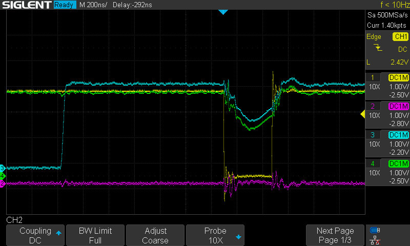
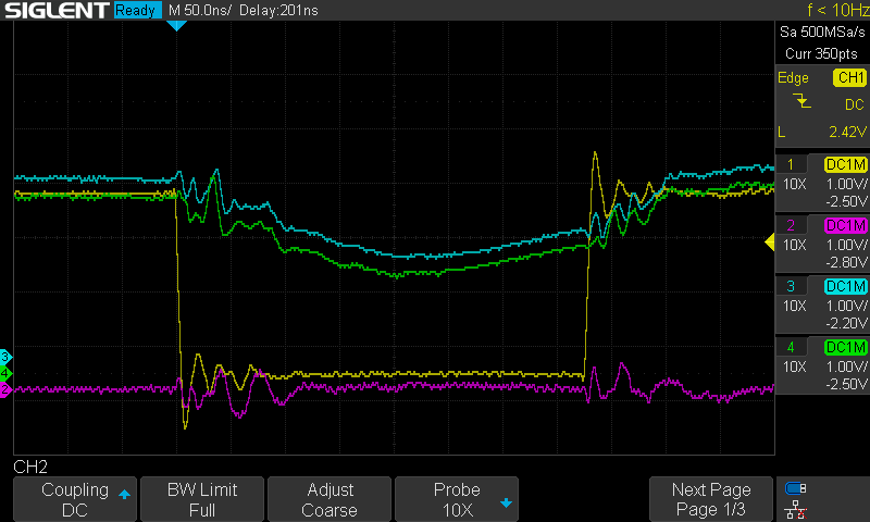
In the captures below you can see a succesfull glitch of the variable in register loop.
- Channel 1 (yellow) is the input to the A, B and C pins of the MAX4619
- Channel 2 (magenta) is the PIC pin that will be raised when the glitch fails (event not shown here)
- Channel 3 (cyan) is the PIC pin that will be raised when the loop starts
- Channel 4 (green) is the power supply to the PIC
For additional information on the wiring see the hardware folder, and for
additional information on the code running on the PIC see the target_src
folder.

