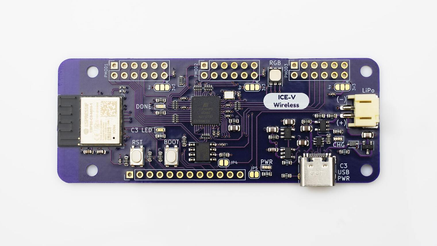
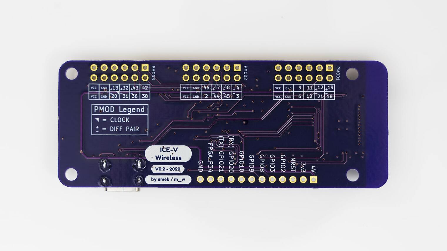
Combined ESP32C3 and iCE40 FPGA board
This project combines an Espressif ESP32-C3-MINI-1 (which includes 4MB of flash in the module) with a Lattice iCE40UP5k-SG48 FPGA to allow WiFi and Bluetooth control of the FPGA. ESP32 and FPGA I/O is mostly uncommitted except for the pins used for SPI communication between ESP32 and FPGA. Several of the ESP32C3 GPIO pins are available for additonal interfaces such as serial, ADC, I2C, etc.
This project comprises both hardware, firmware, gateware and host-side communication utilities.
The hardware design is provided as schematic and layout in KiCAD 6 format. The design provides:
- Three standard PMOD connectors spaced to accommodate
dual-PMOD modules with all eight signal pins directly connected to the
FPGA.
- Many PMOD signals are available in differential pairs with the positive and negative halves on adjacent odd/even pins.
- PMOD power pins can be tied either to the on-board regulated 3.3V supply (default) or to the unregulated ~4V supply (requires cutting a trace and adding a solder blob).
- Additional I/O connector with seven ESP32C3 GPIO lines and one FPGA line, along with power, ground and reset connections.
- 8MB PSRAM connected directly to the FPGA.
- USB-C connector for power, programming and JTAG debugging of the ESP32C3.
- Tactile buttons for reset and boot mode selection of the ESP32C3.
- RGB LED directly driven by the iCE40 FPGA
- LED indicators for power, charging, FPGA configuration and ESP32C3 software.
- LiPo Battery operation and charging.
- Onboard antenna for WiFi and Bluetooth.
The ESP32 firmware is written in C with the ESP-IDF V5.0 toolchain and libraries. Initially it provides a TCP socket interface over WiFi with the following features:
- Initial loading of the FPGA configuration at powerup from a SPIFFS filesystem
contained in the ESP32C3F[H/N]4 flash.
(See Page 9 of the ESP32-C3 Series Datasheet for part number details). - WiFi socket-based "instant" loading of configurations direct to the FPGA.
- WiFi socket-based updating of the configuration stored in SPIFFS.
- WiFi socket-based monitor/control of the FPGA design via SPI.
- WiFi socket-based monitor of LiPo battery voltage (requires added solder blob).
The iCE40 FPGA gateware provided is a simple design that demonstrates basic SPI monitor/control via SPI with a flashing LED. More advanced designs are possible.
A command-line Python script is provided to communicate over TCP sockets with the ESP32C3 which supports the features outlined in the Firmware section above.
See here:


