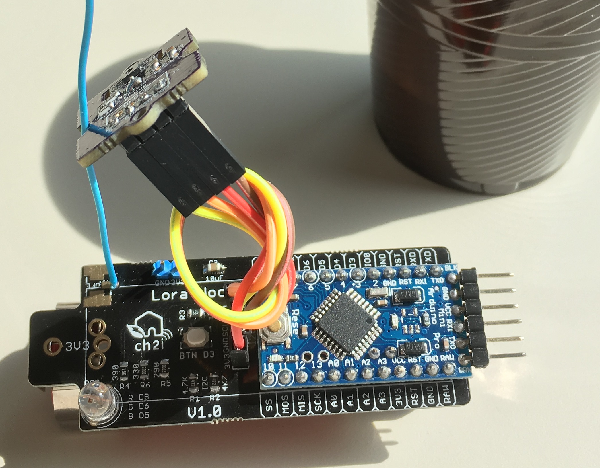
An Arduino core for some of my custom boards such has Mini-Lora that have been optimized with optiboot bootloader and different serial speed to increase and improve uploading. This requires at least Arduino IDE v1.6.2, where v1.8.6+ is recommended.
Also some of the boards have RFM95 LoRa module build in so constants pins are defined so you won't bother looking are the connection when coding. See section Pre defined boards
Your board should have the bootloader already flashed, it's not the scope of this repo. Everything to burn bootloader is explained here
Click on the "Download ZIP" button in the upper right corner. Exctract the ZIP file, and move the extracted folder to the location "~/Documents/Arduino/hardware". Create the "hardware" folder if it doesn't exist.
This folder should match the one you setup into Arduino IDE preference, for example, setup in my IDE for Sketchbook Location is D:\devt\Arduino so I need to extract zip in D:\devt\Arduino\hardware
After extraction, you should have something like D:\devt\Arduino\hardware\ch2i-arduino-boards-master, of course you can rename folder to D:\devt\Arduino\hardware\CH2i
Then, open Arduino IDE, and a new category in the boards menu called "CH2i Boards" will show up.
Ok, so you're downloaded and installed, ready to upload but how to get started? Here's a quick guide:
- Open the Tools > Board menu item, and select a CH2i Boards compatible microcontroller, example
Mini Lora - Select your prefered clock frequency. 16 MHz is standard on most Arduino boards but 3.3V Boards shoudl be 8MHz.
- Select uploading serial speed depending on which bootloader speed you flashed into your Arduino board.
For example, if you flashed bootloader optiboot_flash_atmega328p_250000_8MHZ.hex
- select 8MHz for Clock
- select 250KBps for serial speed
Some boards with LoRa RFM95 module have the pin definition so you can use it in your sketch. If you select the correct board in Arduino IDE you don't need to take care of the values, just use the defined constants, for example LMIC stack
lmic_pinmap lmic_pins = {
    .nss = LORA_CS,
    .rxtx = LMIC_UNUSED_PIN,
    .rst = LORA_RESET,
    .dio = {LORA_DIO0, LORA_DIO1, LORA_DIO2},
};
Also you can check at compile time the board used (selected in Arduino IDE)
#if defined (AVR_MINILORA)
// Blah Blah
#elif defined (AVR_LORADUINO)
// Blah Blah
#elif defined (AVR_LORARADIONODE)
// Blah Blah
#else
#error "Unknown board selected"
#endif
Like that, you don't need to change sketch whatever board you use for LoRa pinout. Here are below the pins definition made for each board
#define LED_BUILTIN 13
#define LED_RED     9
#define LED_GRN     6
#define LED_BLU     5
#define LED_PWM

#define BTN_ACTION 3

#define LORA_DIO0  2
#define LORA_DIO1  7
#define LORA_DIO2  8
#define LORA_RESET 9
#define LORA_CS SS#define LED_BUILTIN 13
// Take care DIO pins are not connected to Digital Pin
// by default, you need to solder the one needed on connector
#define LORA_DIO0 2
#define LORA_DIO1 5
#define LORA_DIO2 6
#define LORA_DIO3 7
#define LORA_DIO5 8
#define LORA_RESET 9
#define LORA_CS SS#define LED_BUILTIN 7
#define BAT_ANALOG A7
#define BTN_ACTION 5
#define FLASH_CS 8
#define LORA_DIO0 2
#define LORA_DIO1 4
#define LORA_RESET 9
#define LORA_CS SS

