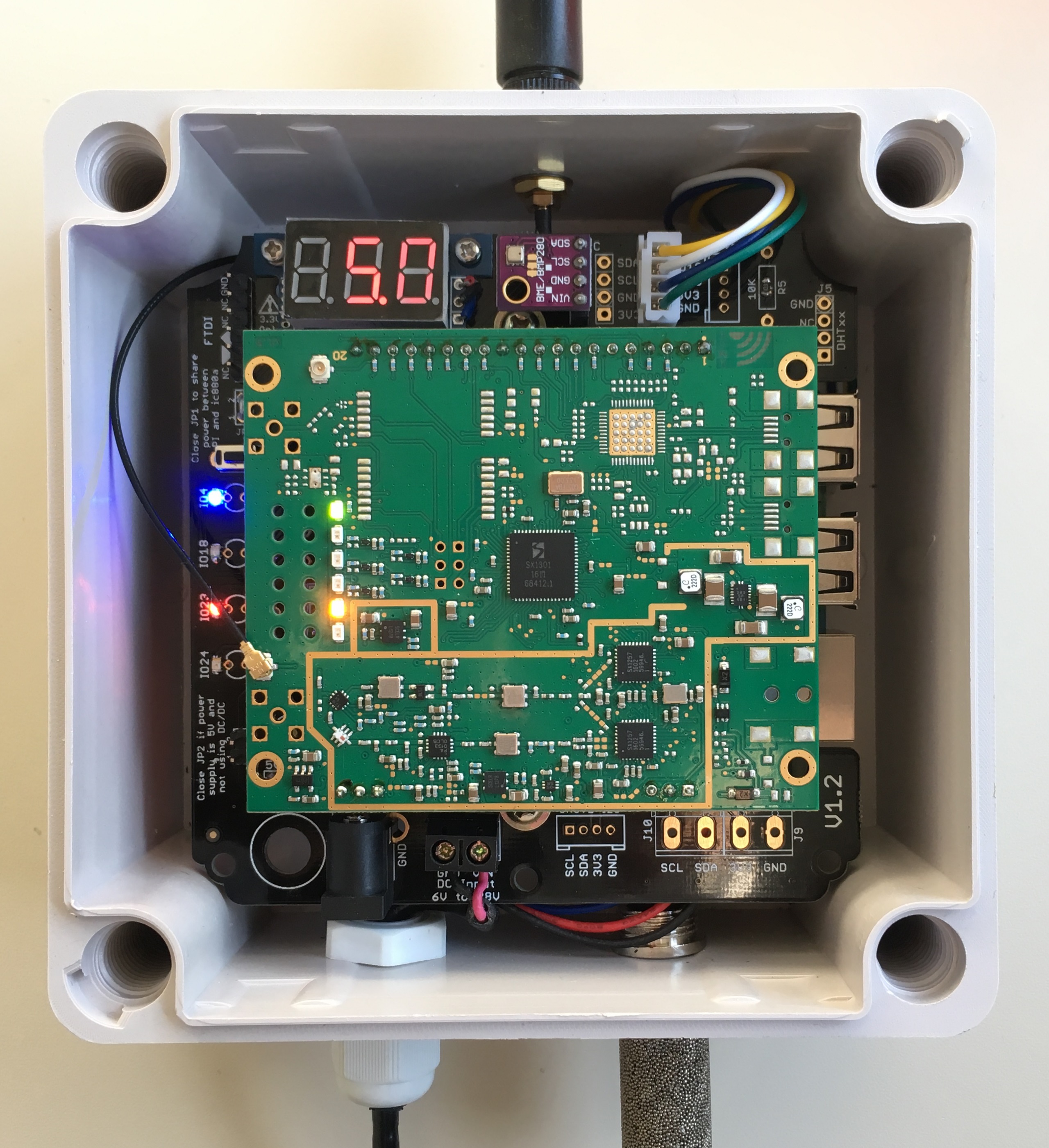
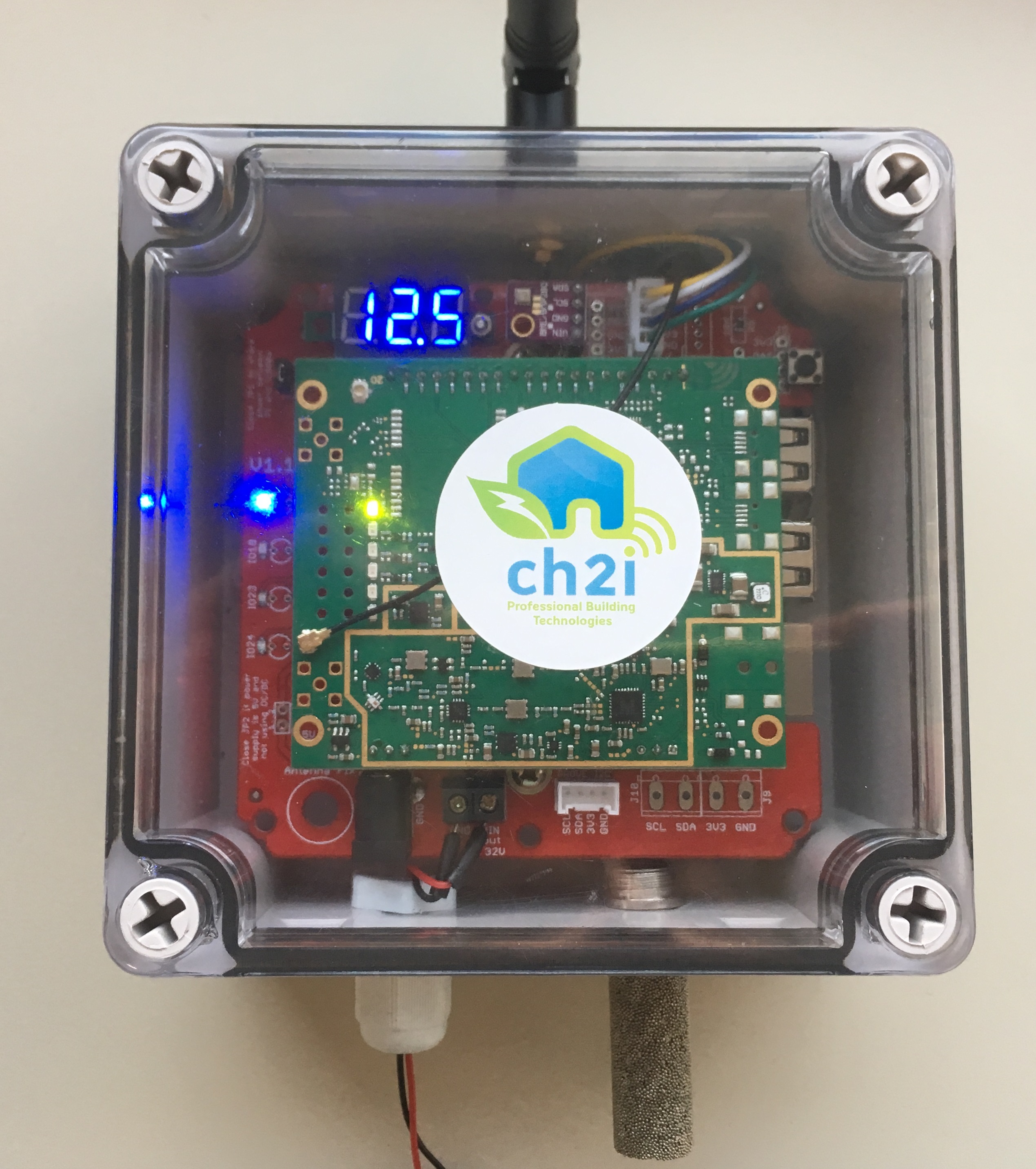
At the begining this shield has been created to help wiring between Raspberry PI and ISMT iC880A LoraWan concentrator Gateway (SPI version) and to be able to put the whole thing into a outdoor enclosure such as this one.
Then I decided to add some funky stuff like:
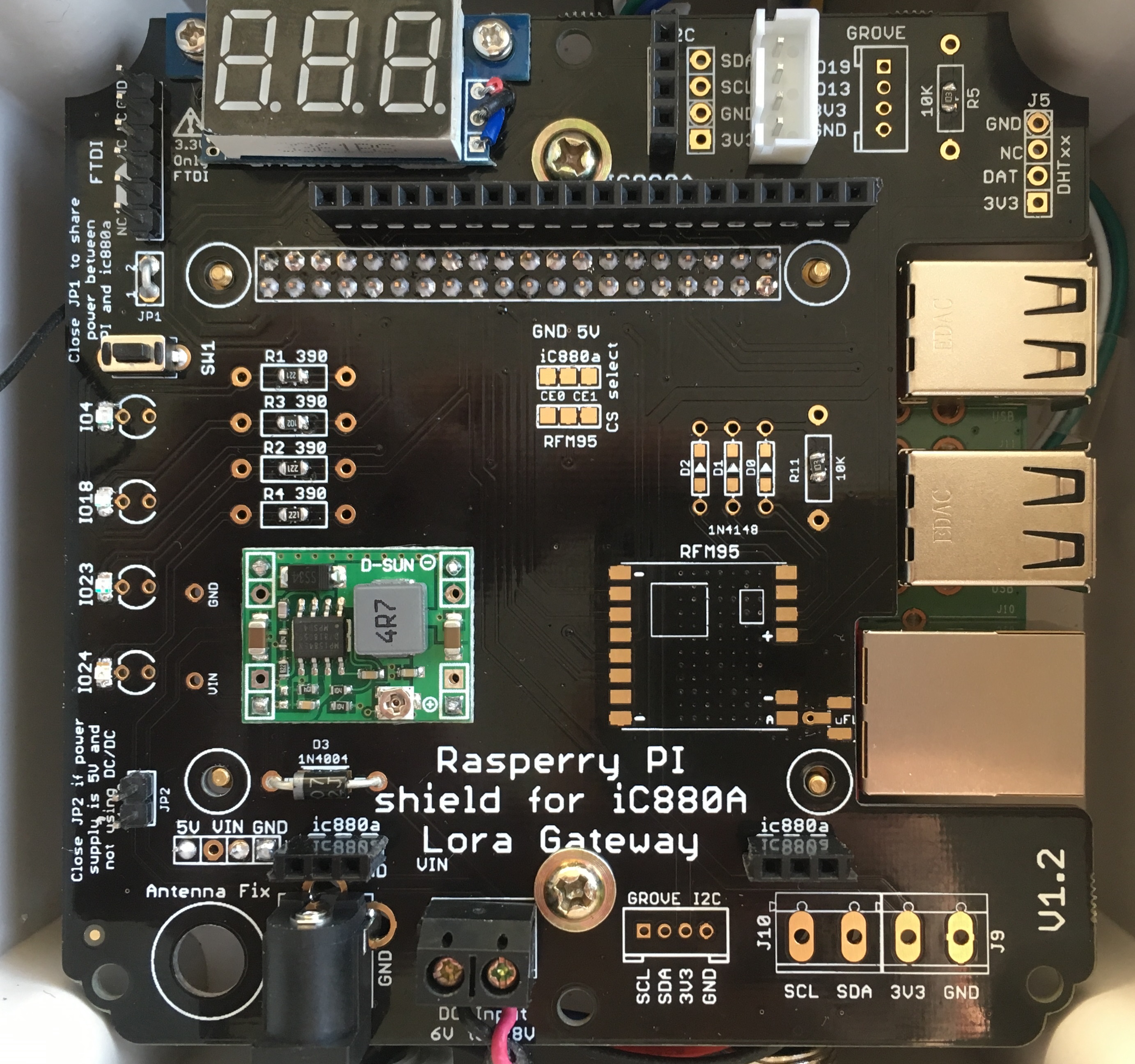
New in V1.2 (tested, working fine)
- Added push button on GPIO19 to be able to shutdown PI Locally (if you don't use RFM95 with IRQ)
- Reversed DHT connector #4
- Added FTDI connector to be able to take hand on PI console when in enclosure (lost network or whatever, no more need to get all off the enclosure and connect HDMI cable to see what's going on)
- Added footprint for excellent Murata OKI-78SR-5 DC/DC 5V
- Fixed Mini Voltmeter Holes Spacing
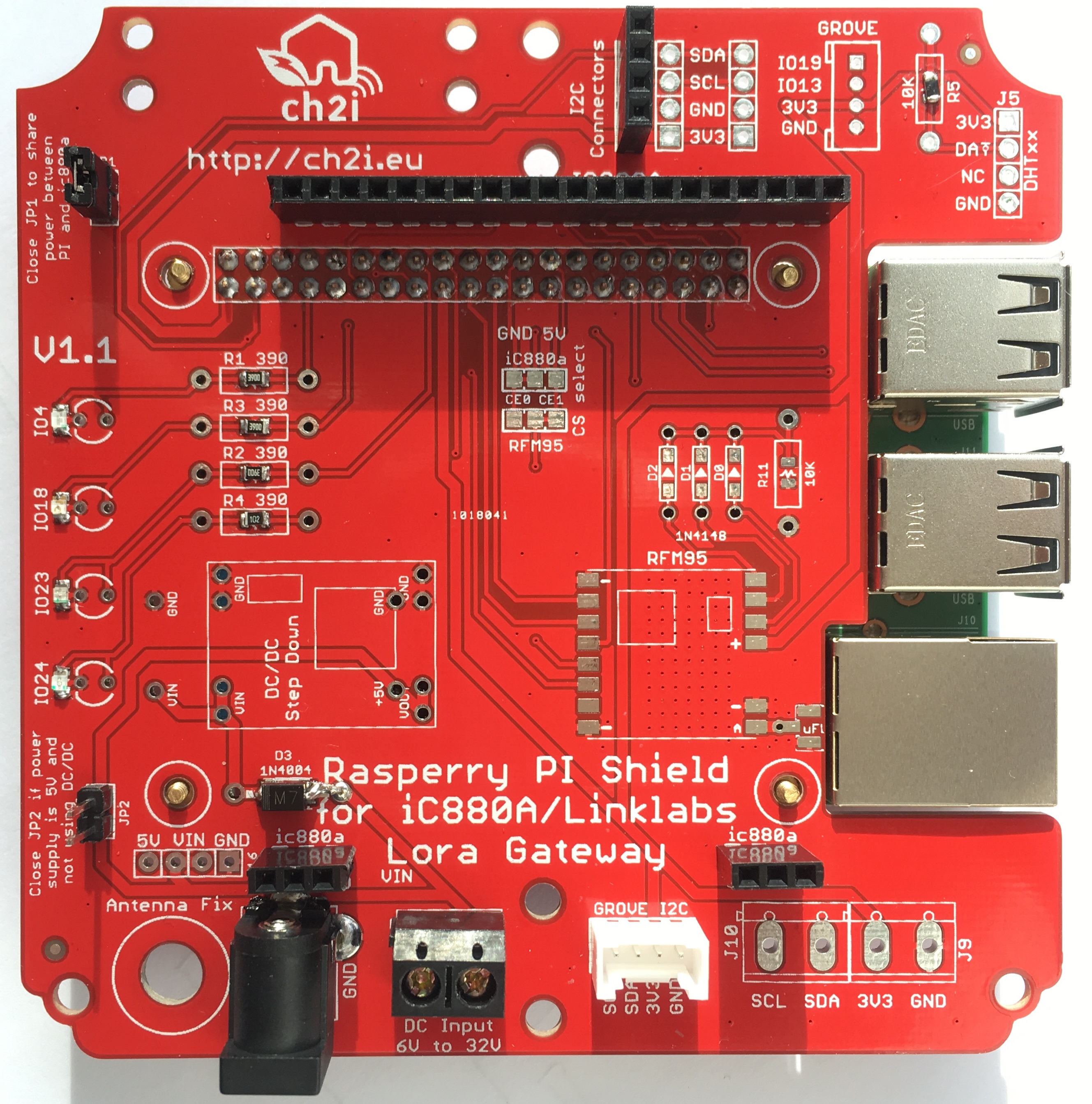
Still V1.1
- Footprint for iC880a ISMT LoraWan concentrator (main goal)
Can be also used between LinkLabs board and Raspi- I2C and Grove connectors to be able to add internal/external sensors such as BME280, SI7021 or HTU21D
- Footprint for DC/DC step down if you want to do some simple POE splitter to power the whole thing thru a network cable or any power
- Footprint for a simple Lora module such as RFM95 that can be used a Single Channel Gateway or also act as a Lora Node
- Power with DC Barrel connector and terminal block
- Four visual GPIO Led
- Footprint for DHT1x Temperature/Humidity sensors
- Easy to build and solder, 0805 or PTH components
- Holes to fix board on enclosure or other support
No specific documentation for now, it's just a kind of wiring helper, please see Gateway section on TTN Wiki and also on TTN Forums for more information on these gateways.
You can power the board with 5V going to Raspberry PI USB power directly, in this case use a descent power supply. You can also use "basic" POE with injector and splitter, this is what I do to oustide (I inject 12V) and use the DC Barrel, in this case I put D4 and a DC/DC Step down calibrated to 5V (do calibration before beforre pluging any boards/devices because default DC/DC output can be over 5V can fry all your boards)
If you need to use sensors you can check out these examples, they're just awesome, I'll post examples as soon as I get all working.
If you use linklabs board you can use these version of packet_forwarder, it has been modified to drive LED of linklabs boards and PPS modem line.
No specific documentation for now, it's just a kind of wiring helper, please see Gateway section on TTN Wiki and Installation is quite easy but as the plate need to go over RPI network and USB connector, you need to use a 2x20 Raspberry PI connector such as this one form adafruit. You can also find some on ebay.
See generic SX1031 Lora Gateway setup for software installation
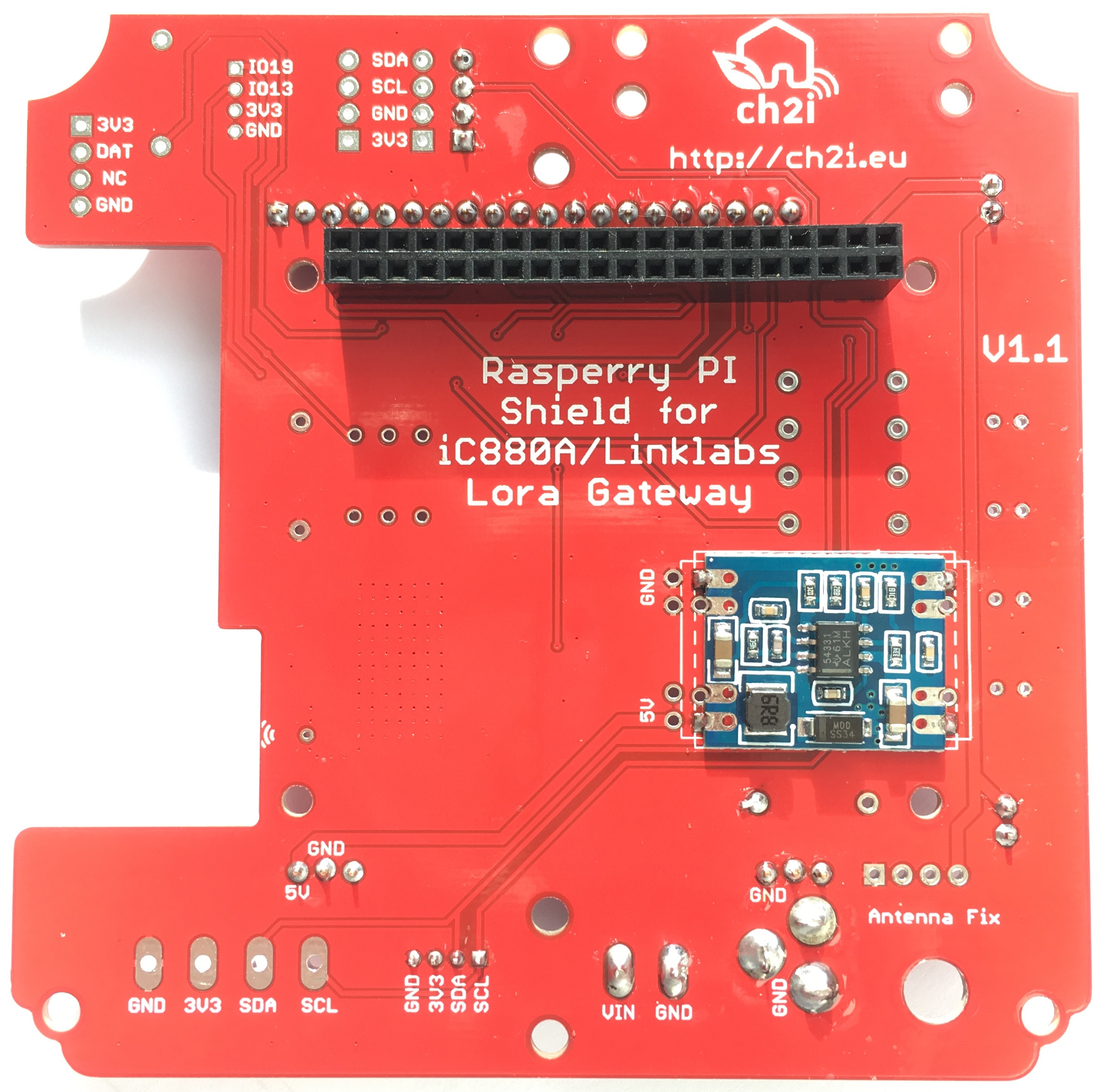
Top side
Bottom side
You can order the PCB of this board on my tindie store located in EU or at PCBs.io (not sure PCBs.io still alive). Don't worry they still have a bug with top/bottom thumbails view but final boards are okay PCBs.io give me some reward when you order my designed boards from their site. This is pretty good, because I can use these rewards to create and design new boards and order boards for a discounted price, so if you don't care about PCB manufacturer please use PCBs.io.

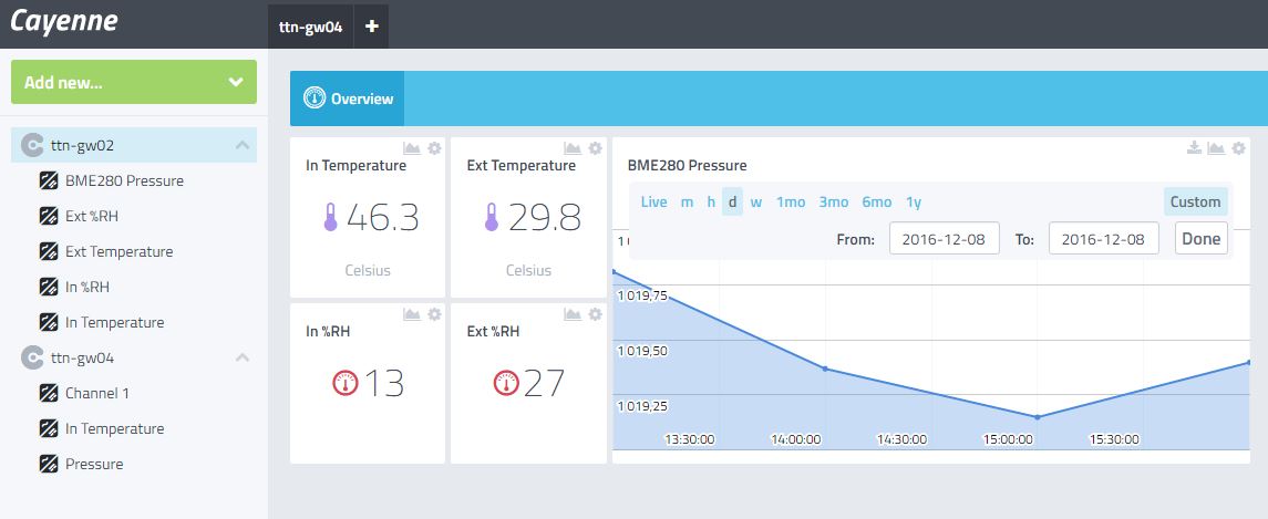
Sensors values en Cayenne (see installer readme for setup)
Nothing fancy, all components are 0805 and/or PTH and can be ordered almost anywhere (digikey, mouser, radiospare, ...). use only what you need dependings on what you want to do.
Adjustable DC/DC step down like this one or this one- Fixed 5V DC/DC step down like this 3A one or this 1.5A one or excellent Murata OKI-78SR-5
- LED for 4 GPIO (4/23/18/24) are 3mm PTH or 0805, color of your choice
- If you use RFM95, diode for DIO0/DIO1/DIO2 (if you want to use interrupts) are 1N4148 PTH or SOD123
- POE Splitter such as these and POE injector as this one
- Terminal blocks are 5MM spacing
- D3 is 1N400x (1N4001, 1N4007, ..) whatever you have, PTH or DO214
- DC/Barell power jack
- Grove connector and others at seeedstudio
Some PI connector with long pins for pluging this board and Linklabs one- Some 2X20 pins PI connector for pluging this board
- Antenna UFL with IPEX cable or SMA if using Lora Module
- Small Enclosure 125x125mm 75mm Height #1 or #2
- optional Outdoor protection sleeve for SI7021/HTU21D
- optional Breakout for enclosure temperature monitoring BME280
- optional tactile switch like this one or for external on enclosure this one (connect button LED to Heatbeat LED (GPIO4)
- optional digital voltmeter to display input voltage
- 2 x M4 Hex Brass Spacer Standoff to fix board on enclosure, (higher give you more space below to put POE splitter for example) 25mm to 35mm is fine

This work is licensed under a Creative Commons Attribution-NonCommercial 4.0 International License
If you want to do commercial stuff with this project, please contact CH2i company so we can organize an simple agreement.
See news and other projects on my blog