MF-LBM: A Portable, Scalable and High-performance Lattice Boltzmann Code for DNS of Flow in Porous Media
Table of Contents
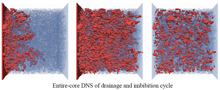
MF-LBM 1 2 is a high-performance lattice Boltzmann (LB) code for direct numerical simulation (DNS) of flow in porous media, primarily developed by Dr. Yu Chen (LANL), under the supervision of Prof. Albert Valocchi (UIUC), Dr. Qinjun Kang (LANL) and Dr. Hari Viswananthan (LANL). 'MF' refers to microfluidics or 'Magic Find'. The code was first developed at University of Illinois at Urbana-Champaign based on a mainstream LB color-gradient multiphase model and further improved at Los Alamos National Laboratory by implementing the Continuum-Surface-Force and geometrical wetting models to reduce spurious currents so that the inertial effects in scCO2 and brine displacement in porous media can be accounted for 2.
- exploring multiple levels of parallelism
- extensively optimized for vectorization
- directive-based parallel programing model supporting CPU, GPU, MIC and ARM
- advanced LB multiphase model (CSF model + geometrical wetting model) ensuring relatively small spurious currents
- overlapped communication and computation
- sample geometry files, pre-processing and post-processing code included
Sample geometry files(in submodule):simple_geometry_tube_sphere: a tube with a spherical obstacle in the centerrock_sample_text_images: text images from cropped Bentheimer sandstone scans 3rock_sample_wall_array_converted: binary file of the wall array converted from text imagesrock_sample_wall_array_processed: binary file of the wall array converted from text images with added buffer layers
Pre-processing code:convert_textimages_to_WallArray: converting text images from rock scans to a single 3D wall array stored in binary formatcreate_geometry_to_WallArray: creating simple geometriesgeometry_modification: modifying the 3D wall array, i.e., adding inlet/outlet buffer layers or croppingwall_boundary_preprocess: computing normal directions of the solid surfaces
Main simulation code:multiphase_3D: 3D multiphase flow simulation code- (coming soon) 3D single phase flow simulation code
Post-processing code:distributed_phi_to_vtk_conversion: for extremely large simulation only, converting distributed phase field data to vtk file for visualizationdistributed_full_flow_field_process: for extremely large simulation only, converting distributed full flow field data for further analysis
Modern manycore processors/coprocessors, such as GPUs and Intel Xeon Phi processors, are developing rapidly and greatly boost computing power. These processors not only provide much higher FLOPS (floating-point operations per second) but also much higher memory bandwidth compared with traditional CPU. One of the most attractive features of the lattice Boltzmann method (LBM) is that it is explicit in time, has nearest neighbor communication, and the computational effort is in the collision step, which is localized at a grid node. For these reasons, the LBM is well suited for manycore processors which require a higher degree of explicit parallelism. The data movement in the LBM is much more intensive than for traditional CFD considering that the D3Q19 lattice model has 19 lattice velocities. Given the current state of computational hardware, in particular the relative speed and capacity of processors and memory, the LBM is a memory-bandwidth-bound numerical method. The high memory bandwidth provided by GPUs or Intel Xeon Phi processors greatly benefits the LBM.
The code is written on Fortran 90 and employs MPI-OpenACC/OpenMP hybrid programing model. The main reason that we chose OpenACC/OpenMP (directive-based parallel programming models) over CUDA is that we want to keep the code portable across different computing platforms so that we are not limited by the NVIDIA GPU solution. As GPU and Intel Xeon Phi processor (and even latest CPU from Intel with AVX512 instructions) rely heavily on SIMT/SIMD, the optimization strategy for these manycore processors/coprocessors are similar, which enables us to achieve reasonable performance across different platforms:
- The AA pattern streaming method is employed to significantly reduce memory access and memory consumption.
- The structure of arrays (SoA) data layout is used to achieve coalesced memory access and maximize vectorization.
- Communication and computation is overlapped to achieve good parallel efficiency, particularly for heterogenous computing platforms.
Chen, Y., Valocchi, A., Kang, Q., & Viswanathan, H. S. (2019). Inertial effects during the process of supercritical CO2 displacing brine in a sandstone: Lattice Boltzmann simulations based on the continuum‐surface‐force and geometrical wetting models. Water Resources Research, 55, 11144– 11165. https://doi.org/10.1029/2019WR025746
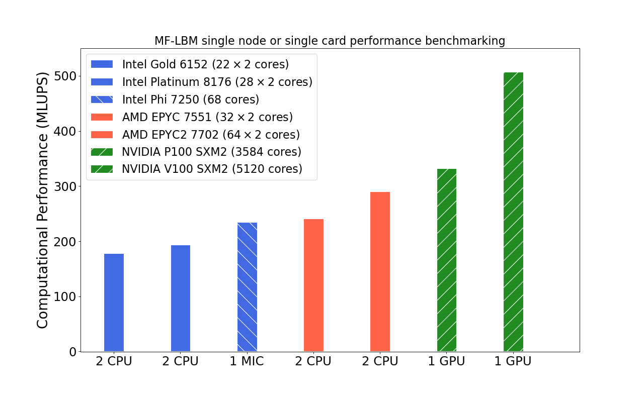
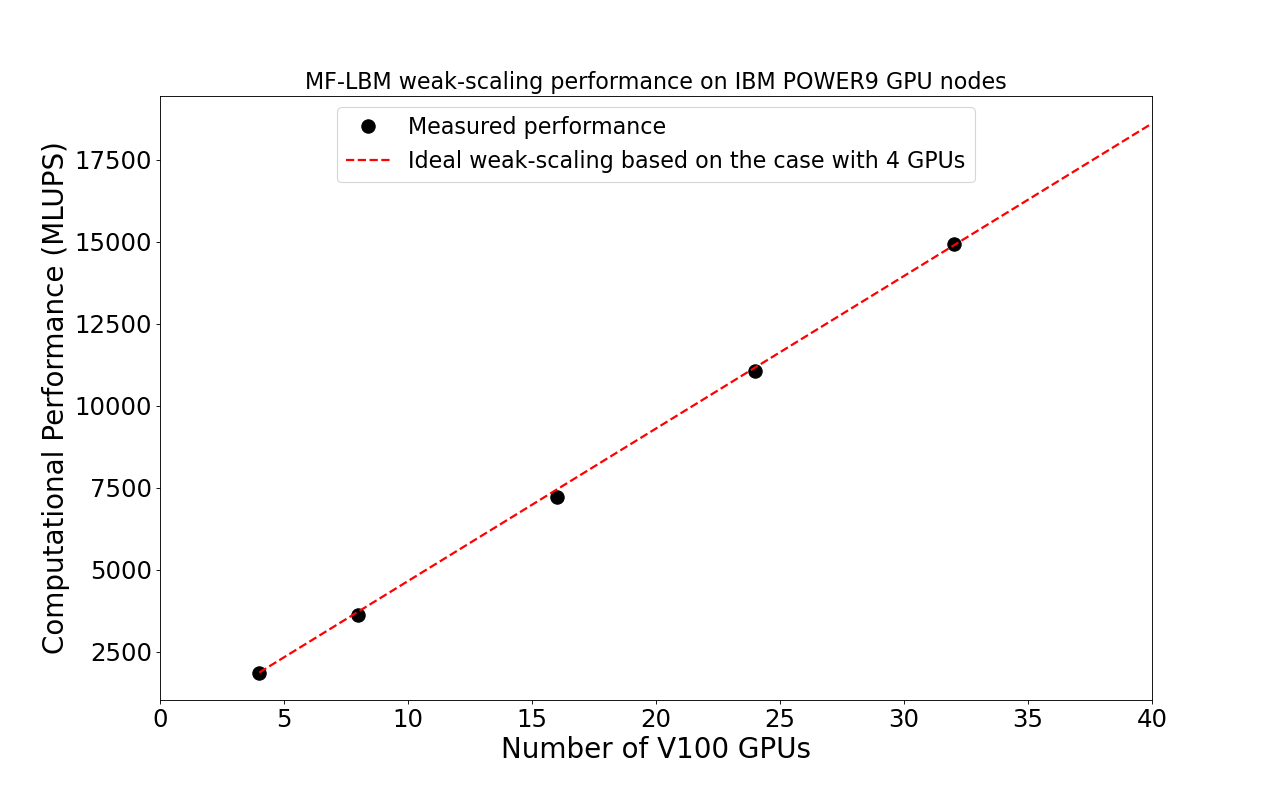
The computational performance benchmarking of MF-LBM was done on the LANL Darwin testbed machine.
Single node/card performance benchmarking is to show the portability of the code.
Scaling up performance benchmarking is to show the scalability of the code.
- A Fortran compiler
- A MPI implementation (most of the run scripts in this repo are based on OpenMPI)
- CUDA toolkit (for NVIDIA GPU platform)
- PGI Fortran compiler (for NVIDIA GPU platform)
- Intel Fortran compiler (for Intel Xeon Phi)
- Make
- Clone the repo
git clone https://github.com/lanl/MF-LBM.git
- Initiate submodules for external non-code files (geometry files used in the test suites)
cd path-to-MF-LBM/MF-LBM-extFiles git submodule init git submodule update - Make
cd path-to-MF-LBM/multiphase_3D- CPU version
# Make necessary changes to the makefile:
# Choose CPU as the architecture option.
# Choose a proper compiler.
# Enabling OpenMP is recommended.
# See instructions in the makefile for more information.
your-preferred-editor makefile
make
# MF_LBM.cpu will be generated
- GPU version
# Make necessary changes to the makefile:
# Choose GPU as the architecture option.
# Choose the PGI compiler (recommended for NVIDIA GPU).
# OpenMP must be disabled.
# See instruction in the makefile for more information.
your-preferred-editor makefile
# Make sure to enable OpenACC in preprocessor.
your-preferred-editor 0.src/preprocessor.h
make
# MF_LBM.gpu will be generated
- MIC (Intel Xeon Phi) version
# Make necessary changes to the makefile:
# Choose MIC as the architecture option.
# Choose a proper compiler (Intel compiler is recommended).
# OpenMP and AVX512 must be enabled for the MIC version.
# See instructions in the makefile for more information.
your-preferred-editor makefile
make
# MF_LBM.mic will be generated
- CPU version
- Configure run scripts (for CPU platform)
cd working_directory
cp path-to-MF-LBM/multiphase_3D/run_template/template-config.sh ./config.sh
# Make necessary changes to config.sh (i.e., input parameters, paths and run command).
# See instruction in template-config.sh for more information.
your-preferred-editor config.sh
./config.sh
# A script, irun.sh, will be generated.

# If OpenMP is enabled (recommended for CPU, MIC, and ARM platform), then run the following command:
# export OMP_NUM_THREADS=n
# , where n is recommended to be the core or thread count of the UMA domain of the CPU.

# At least one MPI rank per UMA domain is recommended.

# For GPU platform, number of MPI processes should equal to the total number of GPUs: one MPI rank per GPU.
- Run the program
# See instruction in template-config.sh and irun.sh for more information.
./irun.sh new
-
convert text images to wall arraycd path-to-MF-LBM/preprocessing/1.convert_textimages_to_WallArray ./compile.sh ./a.outThis example converts rock_sample_text_images to a single wall array stored in binary format. No cropping and modification of the rock geometry are made. Loading a binary wall array is much faster than loading large number of text images. This shall be the first step to read in text images before further modification.
-
cd path-to-MF-LBM/preprocessing/1.create_geometry_to_WallArray
./compile.sh
./a.out
This example creates a tube with a spherical obstacle in the center and stored the corresponding wall array in binary format. One can modify the code to create different geometries.
-
cd path-to-MF-LBM/preprocessing/2.geometry_modification
./compile.sh
./a.out
This example reads in a wall array file rock_sample_wall_array_converted which is converted from rock_sample_text_images, and add buffer layers at the inlet and outlet so that proper boundary conditions can be applied. This code can also be used to crop large samples.
-
cd path-to-MF-LBM/preprocessing/3.wall_boundary_preprocess
./compile.sh
./a.out
This example reads in the processed wall array file rock_sample_wall_array_processed, computes the normal directions of the solid surface on all solid boundary nodes and stores the boundary information in binary format which can be later loaded into the main flow simulation program. Read compile.sh for the compiler information (extremely important) for this example. The same boundary info calculation can be completed in the main flow simulation code (Geometry_preprocessing.F90). However, when the rock sample is relatively large, it is recommended to perform the boundary info calculation before the main simulation and load the boundary info from the external file into the main simulation.
Check out template-simulation_control.txt for more information regarding simulation control. The units used in the simulation control file are all lattice units. One can control capillary number, contact angle, absolute values of surface tension and viscosities to link the simulation with a physical system. In particular, the absolute values of surface tension and viscosities will affect Reynolds number even when the capillary number is fixed. The Ohnesorge number is recommended to control the parameters when inertial effects are not negligible 2.
-
cd working_directory
cp path-to-MF-LBM/test_suites/3D_simulation/1.drop_attached_wall/config.sh ./
# edit config.sh (path and run command based on your system; path does not need to be changed if using the default folder)
your-preferred-editor config.sh
./config.sh
./irun.sh new
This example is used to measure contact angle, where a nonwetting drop (fluid1 drop) is attached to a flat wall (y=1 plane)
-
cd working_directory
cp path-to-MF-LBM/test_suites/3D_simulation/2.drainage/config.sh ./
# edit config.sh (path and run command based on your system; path does not need to be changed if using the default folder)
your-preferred-editor config.sh
./config.sh
./irun.sh new
This example simulates nonwetting fluid1 displacing wetting fluid2 in a square duct until one pore-volume fluid1 is injected.
-
Drainage in a tube with a spherical obstacle# The geometry is created inside the main flow simulation code for convenience (Misc.F90/modify_geometry subroutine). Not the recommended way to run the program. cd working_directory cp path-to-MF-LBM/3d-multiphase/test_suites/3D_simulation/3.drainage_external_geometry/config.sh ./ # edit config.sh (path and run command based on your system; path does not need to be changed if using the default folder) your-preferred-editor config.sh ./config.sh ./irun.sh new
This example simulates nonwetting fluid1 displacing wetting fluid2 in a tube with a spherical obstacle in the center. The tube and spherical obstacle are created inside the simulation code. Simulation stops when the nonwetting fluid reaches outlet.
-
Imbibition in a real rock sample using external rock geometry file# The geometry file is created from the pre-processing code example (MF-LBM-extFiles/geometry_files/sample_rock_geometry_wallarray/bentheimer_in10_240_240_240_out10.dat) cd working_directory cp path-to-MF-LBM/test_suites/3D_simulation/4.imbibition_external_geometry/config.sh ./ # edit config.sh (path and run command based on your system; path does not need to be changed if using the default folder) your-preferred-editor config.sh ./config.sh ./irun.sh new
This example simulates wetting fluid2 displacing nonwetting fluid1 in a real rock sample using external rock geometry file. Simulation stops when one pore-volume fluid2 is injected.
-
Steady state relative permeability measurement# The geometry file is created from the pre-processing code example (MF-LBM-extFiles/geometry_files/sample_rock_geometry_wallarray/bentheimer_in10_240_240_240_out10.dat). The boundary info file need to be created use the wall_boundary_preprocess code (preprocessing/3.wall_boundary_preprocess) cd path-to-MF-LBM/preprocessing/3.wall_boundary_preprocess ./compile.sh ./a.out cd working_directory cp path-to-MF-LBM/3d-multiphase/test_suites/3D_simulation/5.fractional_flow_external_geometry_preprocessed/config.sh ./ # edit config.sh (path and run command based on your system; path does not need to be changed if using the default folder) # specify the paths of the geometry file and solid-boundary-info file on config.sh your-preferred-editor config.sh ./config_sim.sh ./irun.sh new
This example simulates body force driven fractional flow for steady state relative permeability measurement, using external rock geometry file and corresponding pre-computed boundary info file.
-
# The geometry file is created from pre-processing code example (MF-LBM-extFiles/geometry_files/sample_rock_geometry_wallarray/bentheimer_in10_240_240_240_out10.dat). The boundary info file need to be created use the wall_boundary_preprocess code (preprocessing/3.wall_boundary_preprocess)
cd path-to-MF-LBM/preprocessing/3.wall_boundary_preprocess
./compile.sh
./a.out

cd working_directory
cp path-to-MF-LBM/3d-multiphase/test_suites/3D_simulation/6.performance_benchmarking/config.sh ./
# edit config.sh (path and run command based on your system; path does not need to be changed if using the default folder)
# specify the paths of the geometry file and solid-boundary-info file on config.sh
your-preferred-editor config.sh
./config_sim.sh
./irun.sh new
This example is identical to the previous example except that the benchmarking command is enabled in configuration file. The simulation will run 100 time steps and give the computational performance in MLUPS (million lattices update per second). Due to the size of the sample, this example is recommended for benchmarking performance on a single computing node or GPU card.
Three output directories will be created:
- out1.output: bulk properties (i.e., saturation, flow rate) against time. See Monitor.F90 for more information.
- out2.checkpoint: checkpoint data used to restart simulation. See IO_multiphase.F90 for more information.
- out3.field_data: legacy vtk files for flow analysis. See IO_multiphase.F90 for more information. For extremely large simulation (extreme_large_sim_cmd=1 in template-simulation_control.txt), distributed flow field data will be stored for performance consideration. Post-processing code is provided to process those distributed data.
-
Best practice of running MF-LBM on different platforms:
- AVX512 is recommended to be enabled for Intel CPUs that support AVX512. AVX512 must be enabled for Intel Xeon Phi processors.
- Multithreading generally improves performance for this code. However, for small probelms, if there are already many CPU cores (i.e., an AMD 64-core CPU), multithreading many not bring any benefits.
- GPUs require a high degree of parallelism, where a small domain problem may not utilize the full potential of a GPU. Recommended domain size per GPU: from
$200^3$ until GPU memory full.
-
Contact angle:
The contact angle in the control file must be less or equal to 90 degrees due to the particular numerical scheme used, meaning that fluid1 and fluid2 will always be the nonwetting phase and wetting phase, respectively. Drainage and imbibition can be completed by injecting fluid1 and fluid2 respectively.
-
Run command:
Several sample run commands are listed in template-config.sh. This code employs MPI-OpenMP hybrid programing model for the non-GPU versions, where memory affinity on NUMA architectures is very important to achieve expected performance. One should use one or more MPI ranks per UMA domain to avoid OpenMP parallelization across NUMA domains, and set appropriate socket/NUMA affinity in OpenMPI (or other MPI implementations). Number of threads in OpenMP should not exceed the core count or thread count (if multithreading is enabled) of corresponding UMA.
-
Domain decomposition:
Domain decomposition along X direction is no longer supported in the main simulation code for the moment, due to the consideration of non-vectorized data packing and halo area computation. Domain decompositions along Y and Z direction are usually sufficient as single MPI rank corresponds to tens of CPU cores or a full GPU.
-
GCC10 compiler issue:
Building the code with GCC10 may show error messages like
Type mismatch between actual argument at (1) and actual argument at (2)
This is a known issue with GCC10. Use GCC10 new option -fallow-argument-mismatch to turn these errors to warnings for the moment.
Distributed under the BSD-3 License. See LICENSE for more information.
© 2021. Triad National Security, LLC. All rights reserved.
This program was produced under U.S. Government contract 89233218CNA000001 for Los Alamos National Laboratory (LANL), which is operated by Triad National Security, LLC for the U.S. Department of Energy/National Nuclear Security Administration. All rights in the program are reserved by Triad National Security, LLC, and the U.S. Department of Energy/National Nuclear Security Administration. The Government is granted for itself and others acting on its behalf a nonexclusive, paid-up, irrevocable worldwide license in this material to reproduce, prepare derivative works, distribute copies to the public, perform publicly and display publicly, and to permit others to do so.
Dr. Yu Chen - yu_chen_007@outlook.com
MF-LBM-live which is forked from this repo will be used to develop new features by Dr. Yu Chen.
Dr. Qinjun Kang - qkang@lanl.gov


