I always want to build some customized devices for myself, in which I have to implement both the hardware and the software. I am quite familiar with softare development but only with little experience for the hardware development.
To implement the hardware, the most important part seems to be the design of printed circuit board (PCB). And this project aims at gaining such kind of experience.
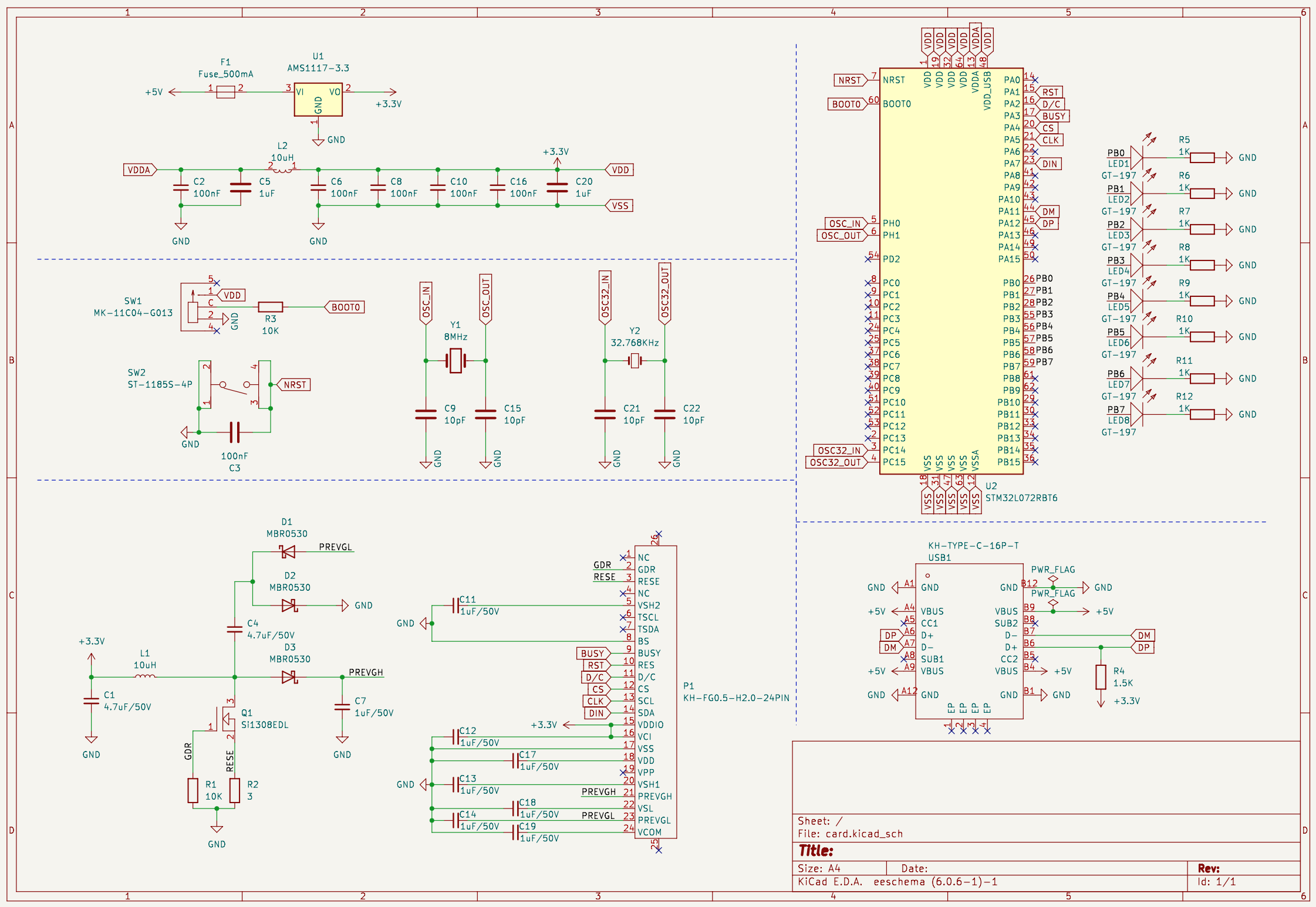
First, I install the KiCad on my mac and I learn how to use it on bilibili. At the beginning, I randomly choose a MCU on 立创商城, which is named as STM32L073RBT6 (about ¥50). Then I try to design the PCB according to this chip.
The most frustrated part in this step is to answer the question about how to driven the STM32L073RBT6 chip. That is, I want to know the “smallest” working requirement of this chip. Besides, I also need to figure out how to achieve these requirements on the PCB. Luckly, after a very long time, I find an article about how to achieve this (STM32L0xx-Hardware).
Another question is to write my program into the chip. I find out that STM32L073RBT6 support USB DFU protocol in STM32-BOOT (section 37.1). And I plan to download my program by a USB type-C port. Now, the question is, how to connect the USB prot to STM32L073RBT6 ? I find the answer in STM32-USB-Hardware (section 3.1.2). The USB port also handles the power supply.
For future concern, I also add a circuit for a 1.54 inch e-paper screen (e-paper-screen).
The final result is like
This step is quite simple because my pcb only runs at low speed.
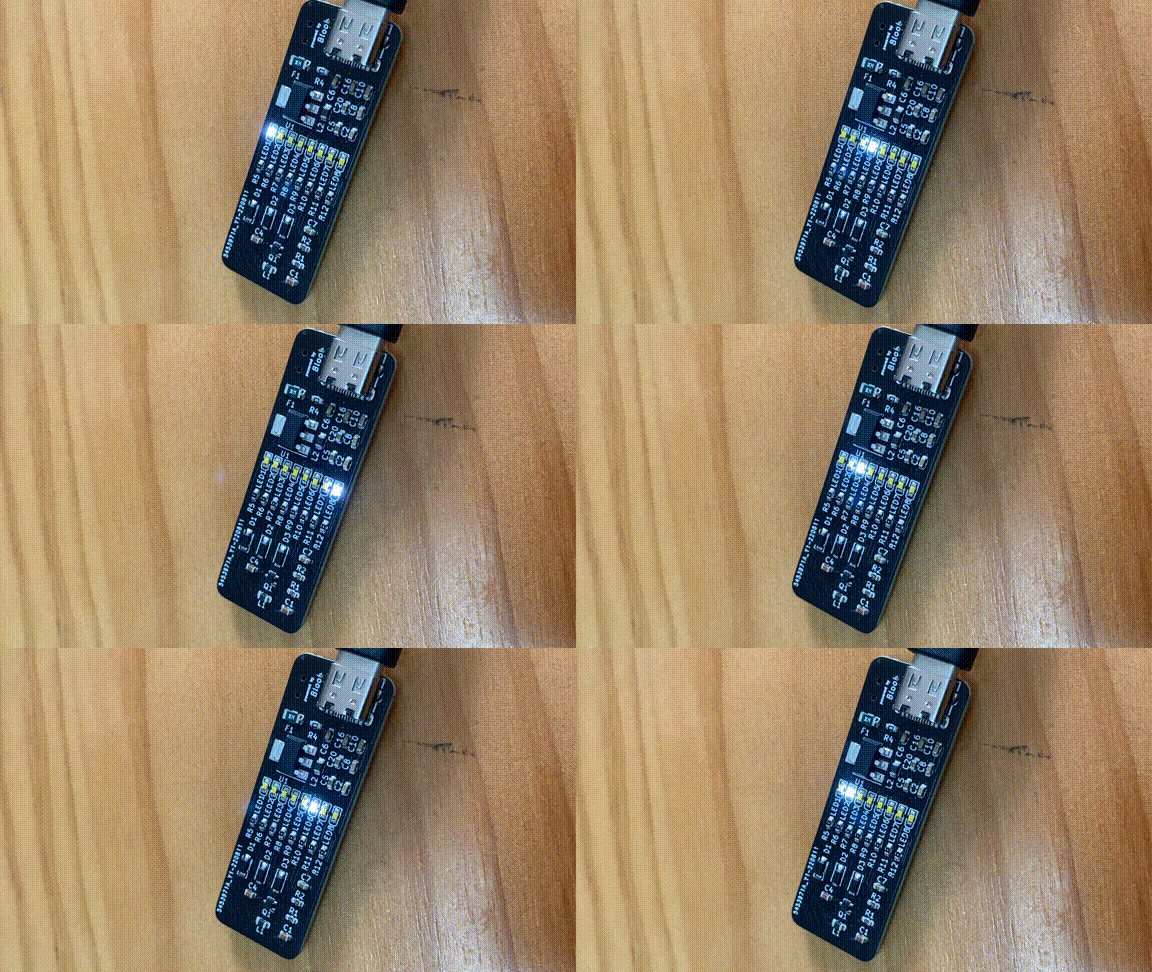
The final result is

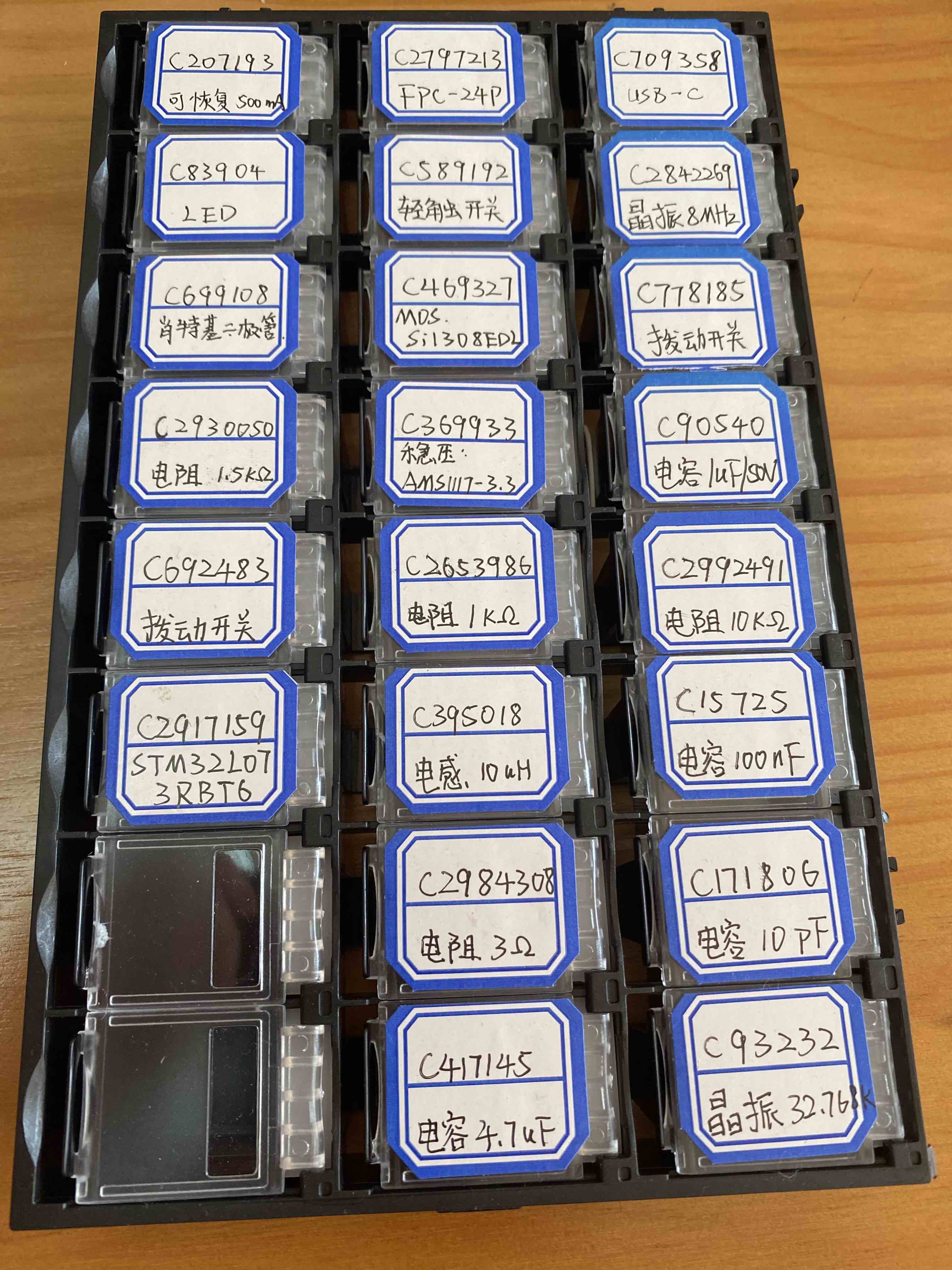
I bought all the materials on 立创商城 (about ¥60/suit) and order the PCB on 嘉立创 (about ¥30 for 5 PCBs).
I assemble and weld these materials by using a heat gun.
Here is the results.
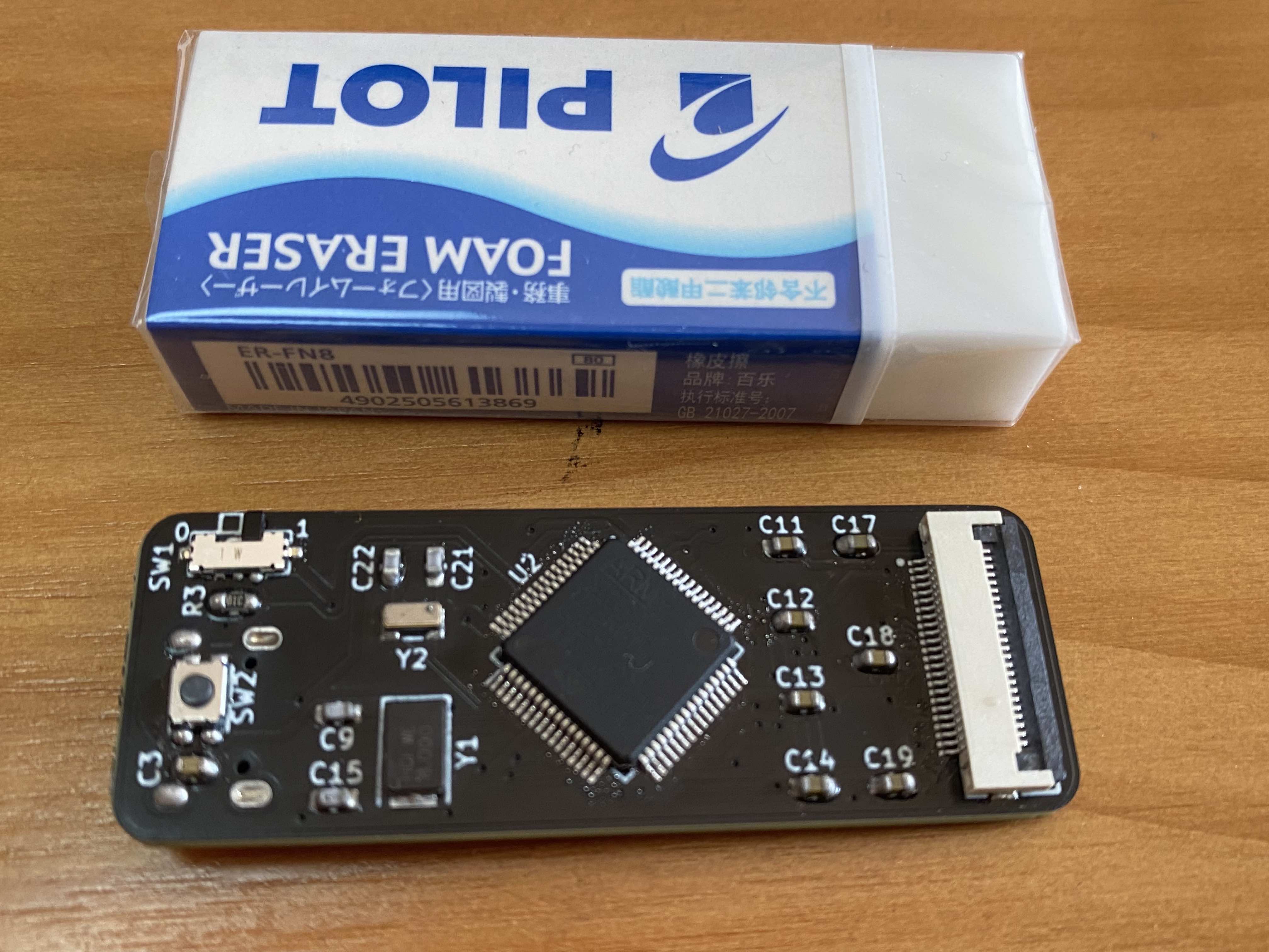
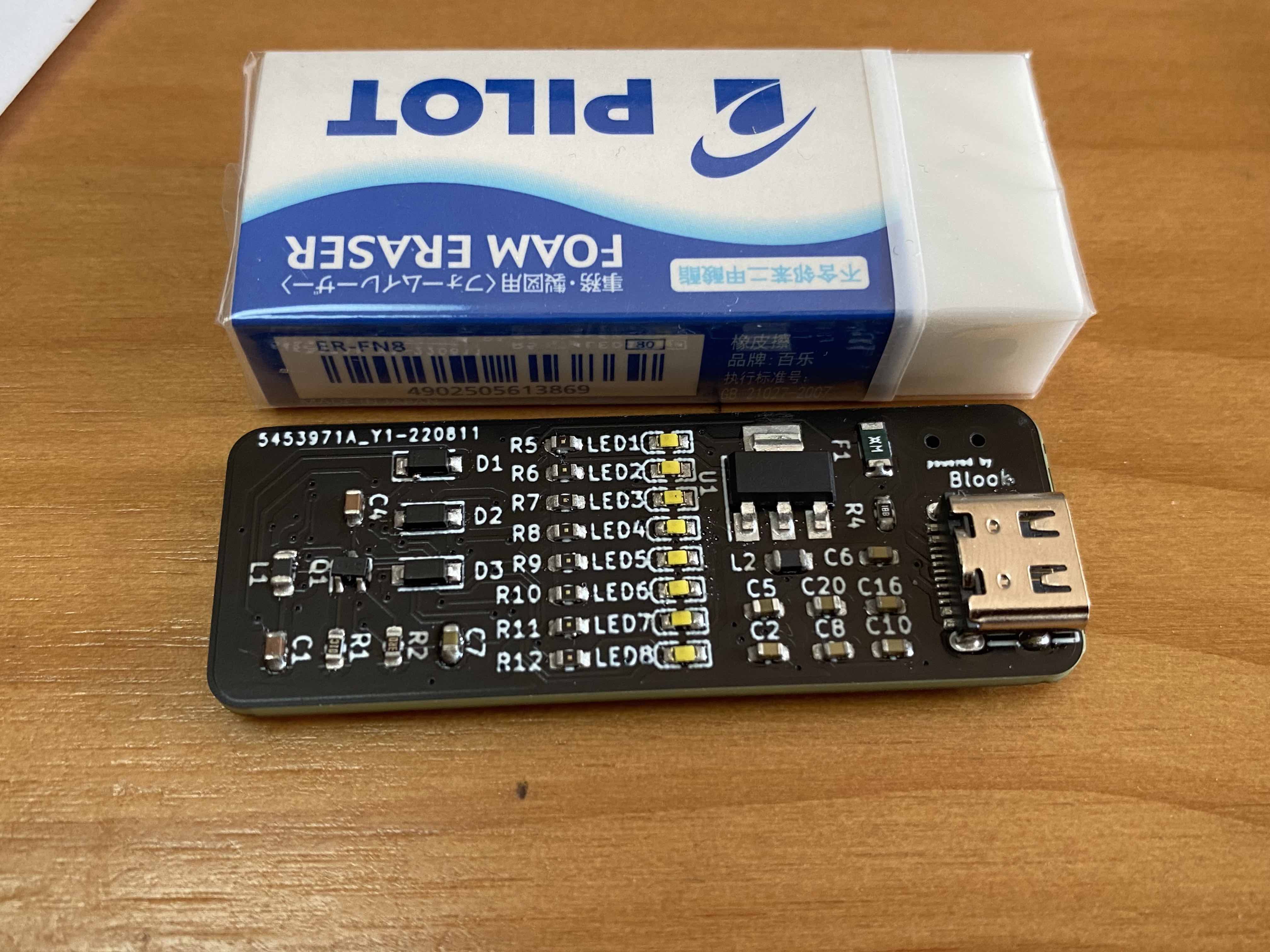
The document provided by ST (STM32L0x3-Manual) is very frustrated to read. It is so long and makes you confused about where to start. The crucial information for us is the boot mechanism of the chip.
The chip has a RAM at 0x20002000 - 0x20004FFF and a read-only flash memory at 0x08000000 - 0x0802FFFF.
When BOOT0 pin is set to 1, the chip runs a hard coded bootloader specified in STM32-BOOT (section 37.1).
This bootloader supports USB DFU protocol, which allows us to download our executables to the chip by the tool dfu-util.
Our program need to be written in the beginning of the flash memory at 0x08000000.
When BOOT0 pin is set to 0, the chip initialized as follows:
- set the 32bit at
0x08000000-0x08000003to registerSP, which always point to the top of the stack (the stack grow towards 0). Typically, these 32bit should be set as0x20004FFFas the bottom of the RAM. - set the 32bit at
0x08000004-0x08000007to registerPC, which is the program counter.
This indicates us about how to initialize in our program.
Now, since we connect the LEDs to the GPIOB ports of the chip, we only need to write 1 to GPIOB port to enlighten the LEDs.
To do this, we need first enable the GPIOB ports at RCC_IOPENR register (STM32L0x3-Manual, section 7.3.12).
(I miss this step at first, and it tooks me a lot of time to figure out what happens).
Then, we need to initialize the GPIOB ports by GPIOB_MODER, GPIOB_OTYPER, GPIOB_OSPEEDR, GPIOB_PUPDR, GPIOB_ODR registers (STM32L0x3-Manual, section 9.4).
These registers could be accessed using certain memory address.
All the code could find at code.
Since I only use USB port to download the program, my PCB lacks debug infrastructure like SWD and ST-Link. So, I cannot do any on-board debugging, which makes it really hard to find out whats going wrong.
Luckily, I could use qemu to simulate the STM32 and run my program on it first. Though the model is not exactly the same, it still helps me a lot. The material on STM32L0x3-Manual for the boot behavior is very ambiguous, you have to do some experiment to figure out what happens.
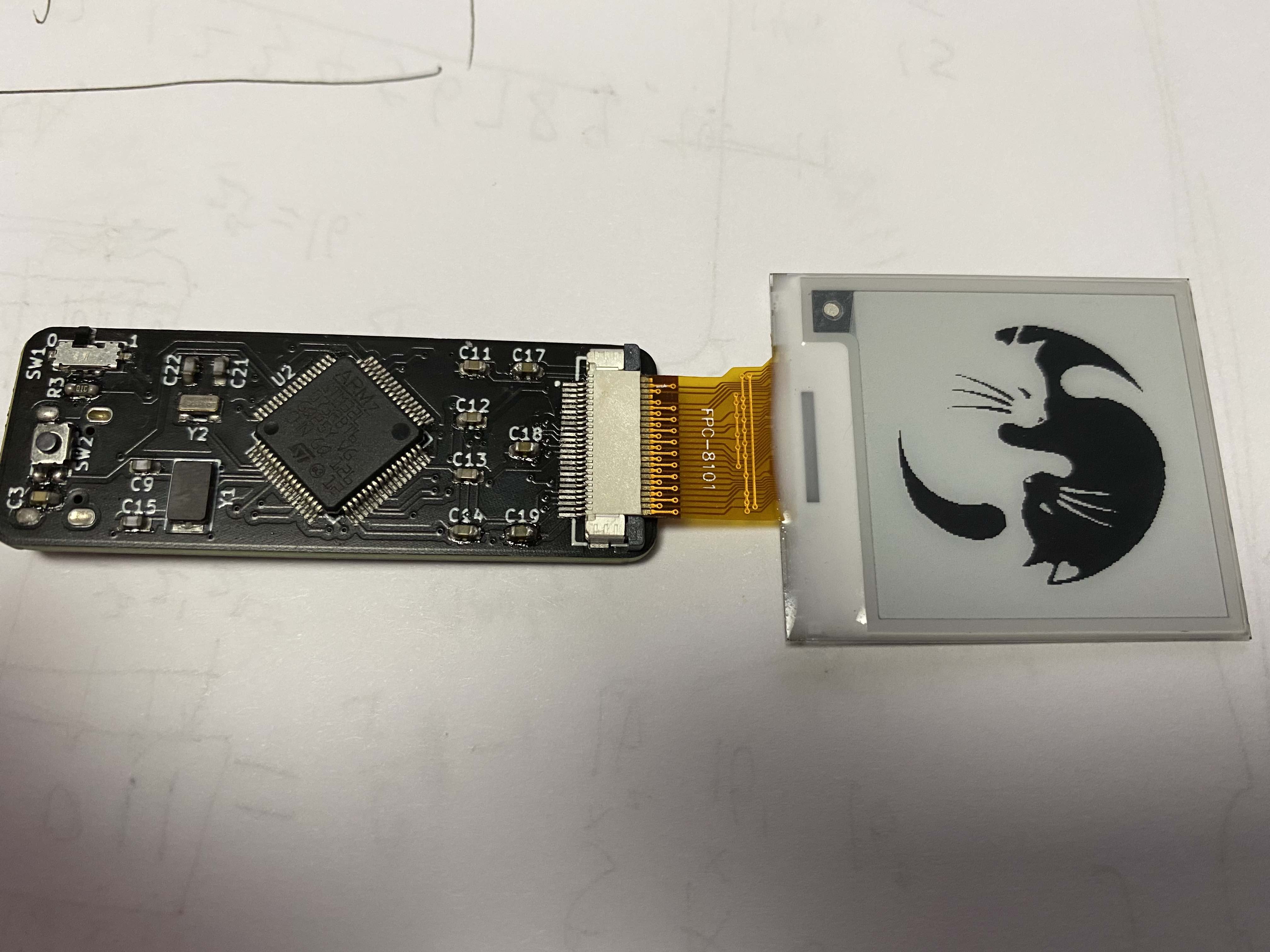
Based on the same hardware, the “card” could be use to drive an e-paper dispaly: wareshare 1.54inch e-paper. During the development, I find that I use the wrong type of FPC connector, the original one is replaced by 0425-A-A04-002 (C2911807). Moreover, the welding is really difficult and it tooks me tons of time to debug.
Most code is generated by a tool called STM32CubeMX.
The code is placed in ./USBLib and could be build using make.
Before using make, one should find an image of 200x200 and run image-bin.py in the folder EPD to convert it into a c header.
