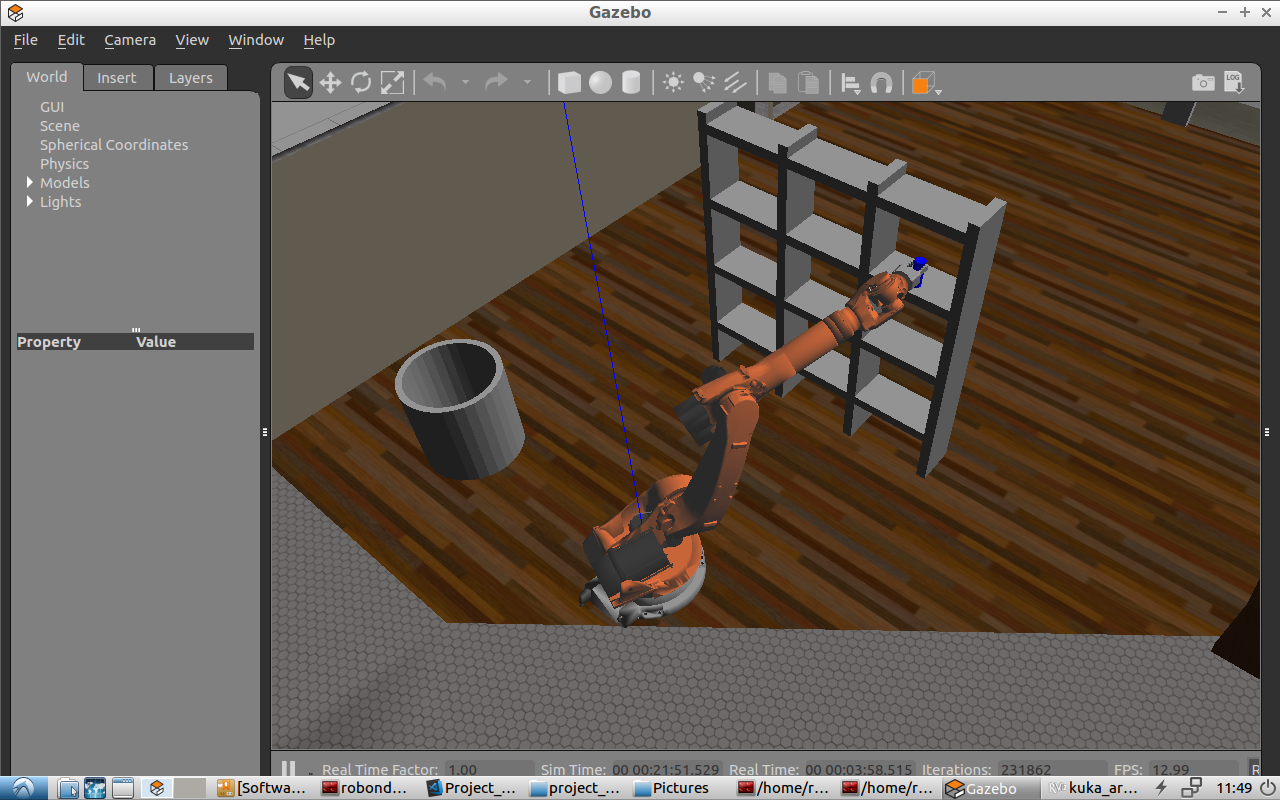
This repositery is forked from Udacity Official RoboND-Kinematics-Project.
I have completed the IK_server.py and IK_debug.py.
This document contains the desciption of works that I have done to complete KUKA210 Pick and Place Project. For environment setup, please go to [this udacity document].(./Project_Intro.md)
Steps to complete the project:
- Set up your ROS Workspace.
- Download or clone the project repository into the src directory of your ROS Workspace.
- Experiment with the forward_kinematics environment and get familiar with the robot.
- Launch in demo mode.
- Perform Kinematic Analysis for the robot following the project rubric.
- Fill in the
IK_server.pywith your Inverse Kinematics code.
1. Provide a Writeup / README that includes all the rubric points and how you addressed each one. You can submit your writeup as markdown or pdf.
This is it :)
1. Run the forward_kinematics demo and evaluate the kr210.urdf.xacro file to perform kinematic analysis of Kuka KR210 robot and derive its DH parameters.
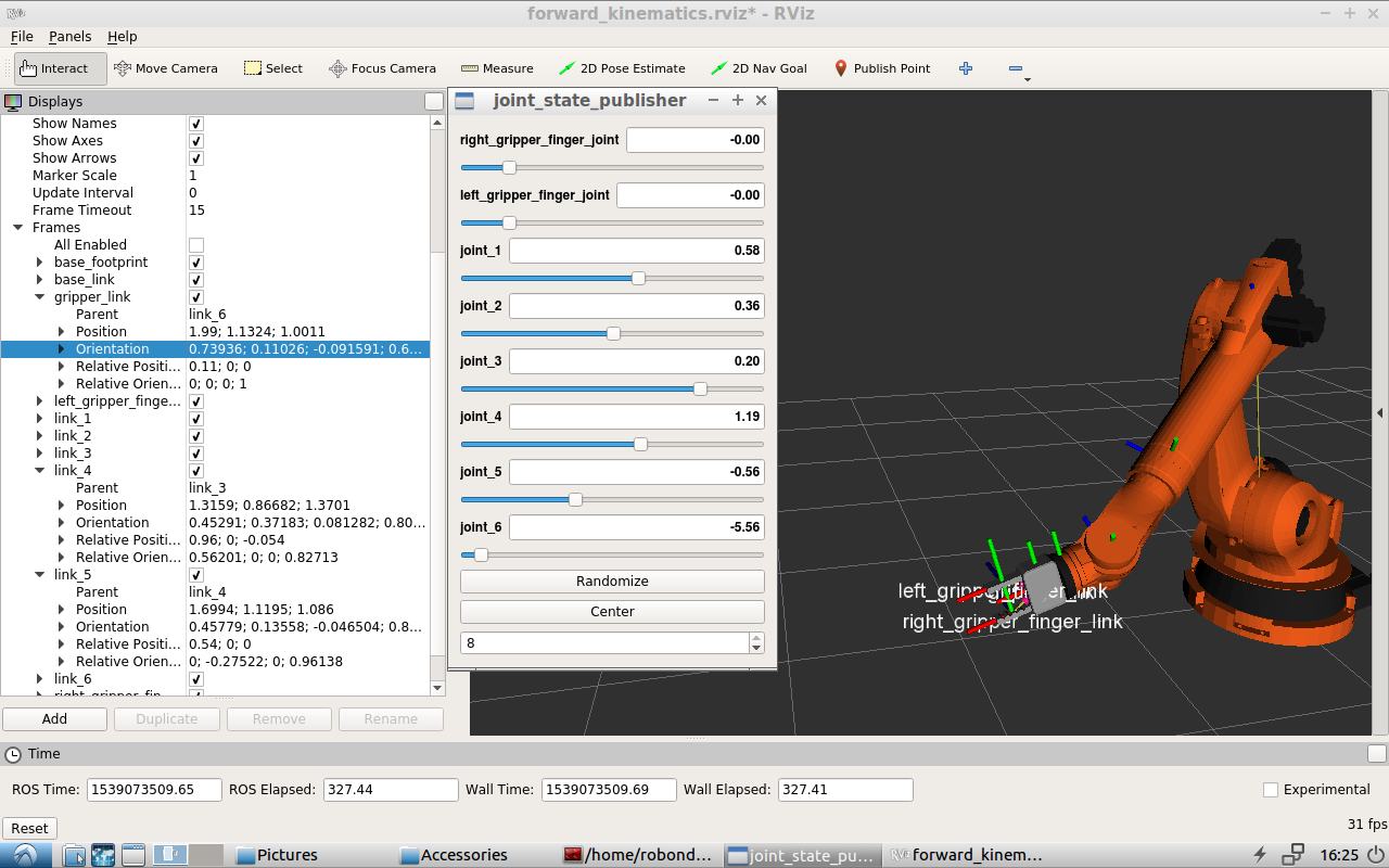
Running the forward_kinematics demo and turning the joint angles in joint_state_pulisher to examine the links postion, especially gripper_link (end effector) and link_5 (wist center), and pose of KR210.
I add this position to be the extra testing case for IK_debug.py:
test_cases = {4:[[[1.99, 1.1324, 1.0011],
        [0.739359, 0.110256, -0.0915909, 0.657877]],
        [1.6961, 1.122, 1.0854],
        [0.58, 0.36, 0.2, 1.19, -0.56, -5.56]]}
2. Using the DH parameter table you derived earlier, create individual transformation matrices about each joint. In addition, also generate a generalized homogeneous transform between base_link and gripper_link using only end-effector(gripper) pose.
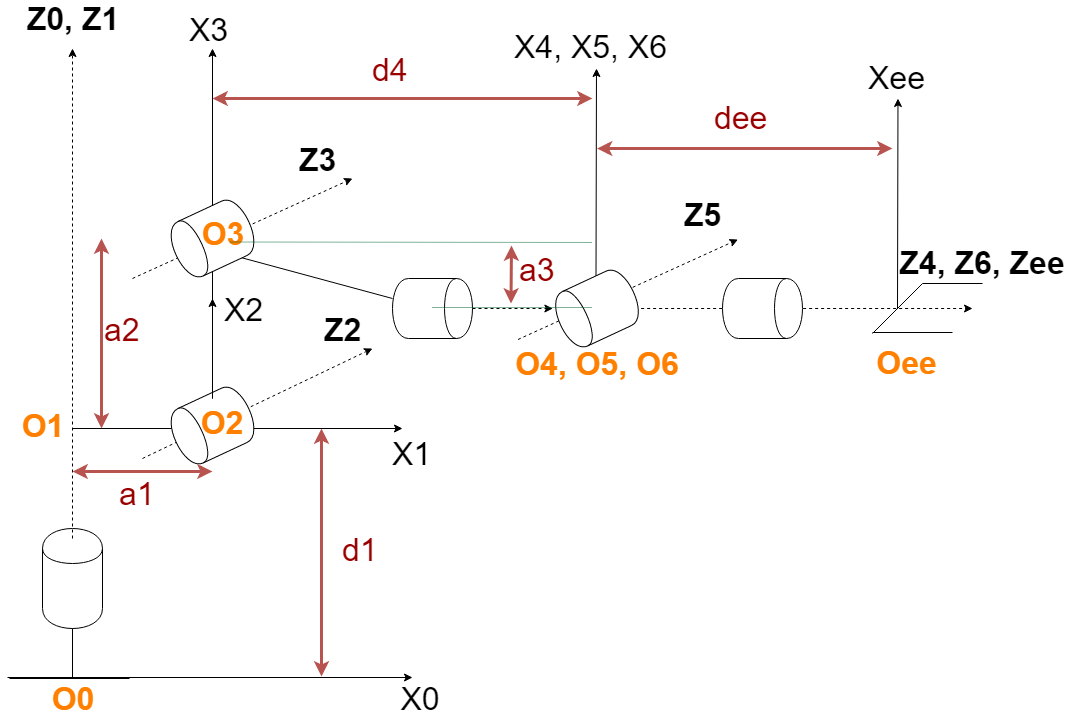
The following graph indicates each DH paramter that is not zero:
Here is the DB Table filled with joint information from kr210.urdf.xacro. Please be noted that since all 6 joints in KR210 is revolute joint, paramter d(i) is fixed according to .urdf file.
| Links | alpha(i-1) | a(i-1) | d(i) | theta(i) |
|---|---|---|---|---|
| 0->1 | 0 | 0 | 0.75 | q1 |
| 1->2 | - pi/2 | 0.35 | 0 | -pi/2 + q2 |
| 2->3 | 0 | 1.25 | 0 | q3 |
| 3->4 | - pi/2 | - 0.054 | 1.5 | q4 |
| 4->5 | pi/2 | 0 | 0 | q5 |
| 5->6 | - pi/2 | 0 | 0 | q6 |
| 6->EE | 0 | 0 | 0.303 | 0 |
For example, a1 is 0.35, which represents the joint distance between joint_1 and joint_2, measuring in x1.
  <joint name="joint_2" type="revolute">
    <origin xyz="0.35 0 0.42" rpy="0 0 0"/>
    <parent link="link_1"/>
    <child link="link_2"/>
    <axis xyz="0 1 0"/>
    <limit lower="${-45*deg}" upper="${85*deg}" effort="300" velocity="${115*deg}"/>
  </joint>
Individual transformation matrices:
# T0_1:
Matrix([[cos(q1), -sin(q1), 0, 0], [sin(q1), cos(q1), 0, 0], [0, 0, 1, 0.75], [0, 0, 0, 1]])
# T1_2:
Matrix([[sin(q2), cos(q2), 0, 0.35], [0, 0, 1, 0], [cos(q2), -sin(q2), 0, 0], [0, 0, 0, 1]])
# T2_3:
Matrix([[cos(q3), -sin(q3), 0, 1.25], [sin(q3), cos(q3), 0, 0], [0, 0, 1, 0], [0, 0, 0, 1]])
# T3_4:
Matrix([[cos(q4), -sin(q4), 0, -0.054], [0, 0, 1, 1.5], [-sin(q4), -cos(q4), 0, 0], [0, 0, 0, 1]])
# T4_5:
Matrix([[cos(q5), -sin(q5), 0, 0], [0, 0, -1, 0], [sin(q5), cos(q5), 0, 0], [0, 0, 0, 1]])
# T5_6:
Matrix([[cos(q6), -sin(q6), 0, 0], [0, 0, 1, 0], [-sin(q6), -cos(q6), 0, 0], [0, 0, 0, 1]])
# T6_EE:
Matrix([[1, 0, 0, 0], [0, 1, 0, 0], [0, 0, 1, 0.303], [0, 0, 0, 1]])
So, total tranformation from base_link to gripper_link is T0_1 * T1_2 * T2_3 * T3_4 * T4_5 * T5_6 * T6_EE
3. Decouple Inverse Kinematics problem into Inverse Position Kinematics and inverse Orientation Kinematics; doing so derive the equations to calculate all individual joint angles.
The following steps show how I find out theta1, theta2 and theta3:
1. Calculate WC(wrist center) position:
# get actual rotation matrix from simulator orientation
R0_6 = simplify(Rot_z(yaw) * Rot_y(pitch) * Rot_x(roll) * R_corr.inv("LU))
nx = R0_6[0, 2]
ny = R0_6[1, 2]
nz = R0_6[2, 2]

# calcute WC(wrist center) position from rotation matrix
wx = px - 0.303 * nx
wy = py - 0.303 * ny
wz = pz - 0.303 * nz
2. Calculate orientation, theta1, theta2 and theta3:
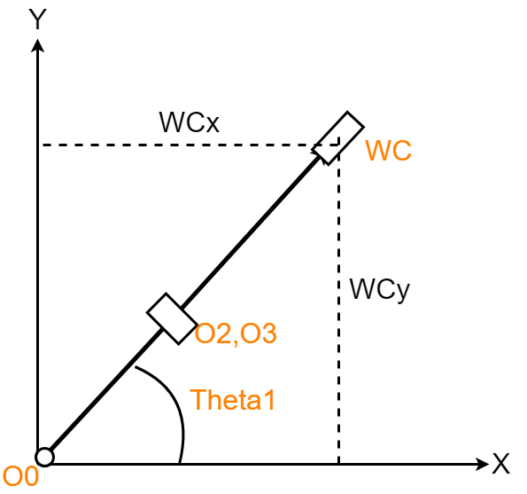
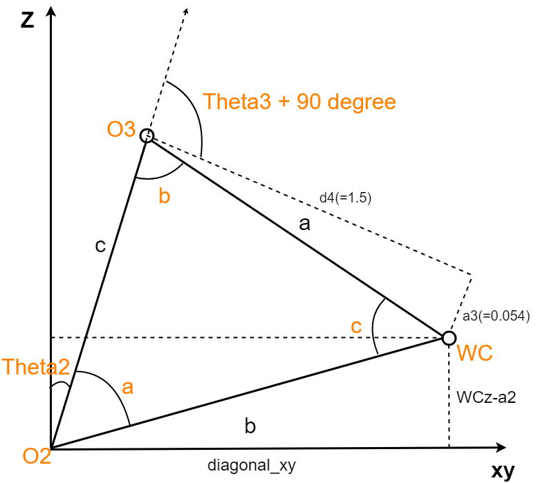
The following graphs show geometry variables:
Code implementation to calculate theta1, theta2 and theta3:
# fixed DH parameter value
d4 = 1.5
d1 = 0.75
a3 = 0.054
a2 = 1.25
a1 = 0.35

# here we need to subtract the length of a1 and d1 to obtain the actual length starting from O2
# line projected from straight distance b/w O2 & WC to plane x y
diagonal_xy = sqrt(wx**2 + wy**2) - a1

length_b = sqrt(diagonal**2 + (wz-d1)**2)
length_a = sqrt(a3**2 + d4**2)
length_c = a2

# Cosine Laws formula:
# length_a**2 = length_b**2 + length_c**2 - 2*length_b*length_c*cos(angle_a)
# inverse to find angle_a, angle_b and angle_c:
angle_a = acos((length_b**2+length_c**2-length_a**2)/(2*length_b*length_c))
angle_b = acos((length_a**2+length_c**2-length_b**2)/(2*length_a*length_c))
angle_c = acos((length_a**2+length_b**2-length_c**2)/(2*length_a*length_b))

# theta 1 to 3:
theta1 = atan2(wy, wx)
theta2 = pi/2 - angle_a - atan2((wz-d1), diagonal_xy)
theta3 = pi/2 - angle_b - atan2(a3, d4)
3. Lastly, use Euler angle composition to find out R3_6 to calculate theta4, theta5 and theta6:
-
From Homogeneous transfromation, since
R0_6 = R0_1 * R1_2 * R2_3 * R3_4 * R4_5 * R5_6, we can decomposeR3_6asR3_4 * R4_5 * R5_6. -
Also, I reuse the tranformation
T0_3to get the rotation matrixR0_3, then further use inverse ofR0_3to calculateR3_6.
R0_3 = T0_3.evalf(subs={q1:theta1, q2:theta2, q3:theta3})[0:3, 0:3]
R0_3 = R0_3.row_join(Matrix([[0], [0], [0]])).col_join(Matrix([[0, 0, 0, 1]]))
R3_6 = simplify(R0_3.inv('LU') * Rrpy)
So, here is the R3_6 rotation matrix we can get:
Matrix([
[-sin(q4)*sin(q6) + cos(q4)*cos(q5)*cos(q6), -sin(q4)*cos(q6) - sin(q6)*cos(q4)*cos(q5), -sin(q5)*cos(q4)],
[                           sin(q5)*cos(q6),                           -sin(q5)*sin(q6),          cos(q5)],
[-sin(q4)*cos(q5)*cos(q6) - sin(q6)*cos(q4),  sin(q4)*sin(q6)*cos(q5) - cos(q4)*cos(q6),  sin(q4)*sin(q5)]])
The following math notation shows how to get each atan2 formula.
Code implementation of each atan2 formula:
theta5 = atan2(sqrt(R3_6[0,2]**2+R3_6[2,2]**2), R3_6[1,2])

if sin(theta5) < 0:
    theta4 = atan2(-R3_6[2,2], R3_6[0,2])
    theta6 = atan2(R3_6[1,1], -R3_6[1,0])
else:
    theta4 = atan2(R3_6[2,2], -R3_6[0,2])
    theta6 = atan2(-R3_6[1,1], R3_6[1,0])
1. Fill in the IK_server.py file with properly commented python code for calculating Inverse Kinematics based on previously performed Kinematic Analysis. Your code must guide the robot to successfully complete 8/10 pick and place cycles. Briefly discuss the code you implemented and your results.
By implementing Pick and place in Gazebo simulator, with IK_server.py up to calculate the inverse kinemeics angles (rosrun kuka_arm IK_server.py), I get 8/10 successful pick and place.
- In the forward kinematics part, I get the total tranformation from
base_linktogripper_linkby combining each joint transformation using DH Table. This is great that it DH table reduces the number of variables needed to be substited because by chosing the right origin in each joint, many paramters are 0
# Define Modified DH Transformation matrix
def transMat(q, d, a, alpha):
    transform = Matrix([
        [cos(q), -sin(q), 0, a],
        [sin(q)*cos(alpha), cos(q)*cos(alpha), -sin(alpha), -sin(alpha)*d],
        [sin(q)*sin(alpha), cos(q)*sin(alpha), cos(alpha), cos(alpha)*d],
        [0, 0, 0, 1]])
    return transform.subs(s)

# Homogeneous transform from base_link to gripper_link
T0_EE = simplify(T0_6 * T6_EE)
-
Also, I did have a hard time figuring out the atan2 variables to calculate Theta4, theta5 and theta6. Eventually, I understand the logic behind. However, I still miss the part of handling singularity problem.
-
The time of calculating inverse kinemetics is quite long, so I can further investigate to try to remove unnecessary calculation steps.
-
I observe that sometimes the path planned is unnecessarily complicated, for example over 40 eef-poses, and the spherical wrist spins a lot. Maybe I can limit the angle of theta4 to theta6 to reduce the spinning times.
