The antithesis of 'keep it simple, stupid' - all the features, all the time.
Do you need...
- To use the Cyboard flex-pcb system? and extend it??
- Two Ultrafalcons...per side?
- SPI devices
- PMW3360/3389 (right side only)
- Dual GC9A01 TFTs per side
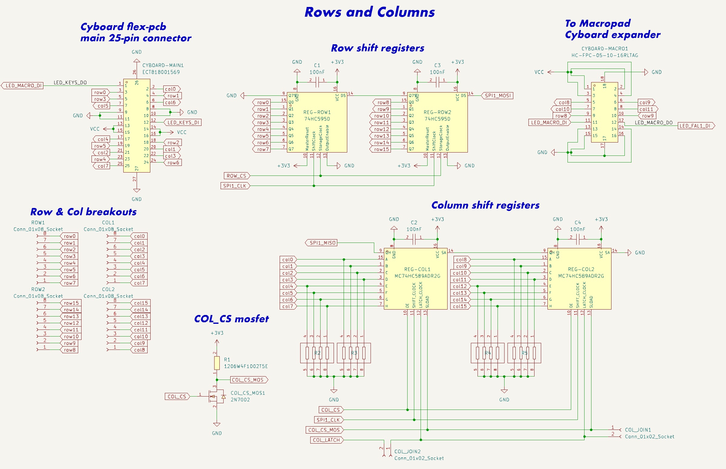
- Quad-shift register-powered 32 pins for rows/cols? (available as a dedicated breakout here)
- 5-way switch or RKJXT for arrow keys?
- Perhaps enough RGB to illumine your entire home? (and almost certainly require 5v supplementary power - a feature, not a bug!)
- Audio and ADC breakouts? Reset switch? Power and debug breakouts?
- And use an existing RP Pico to do it?
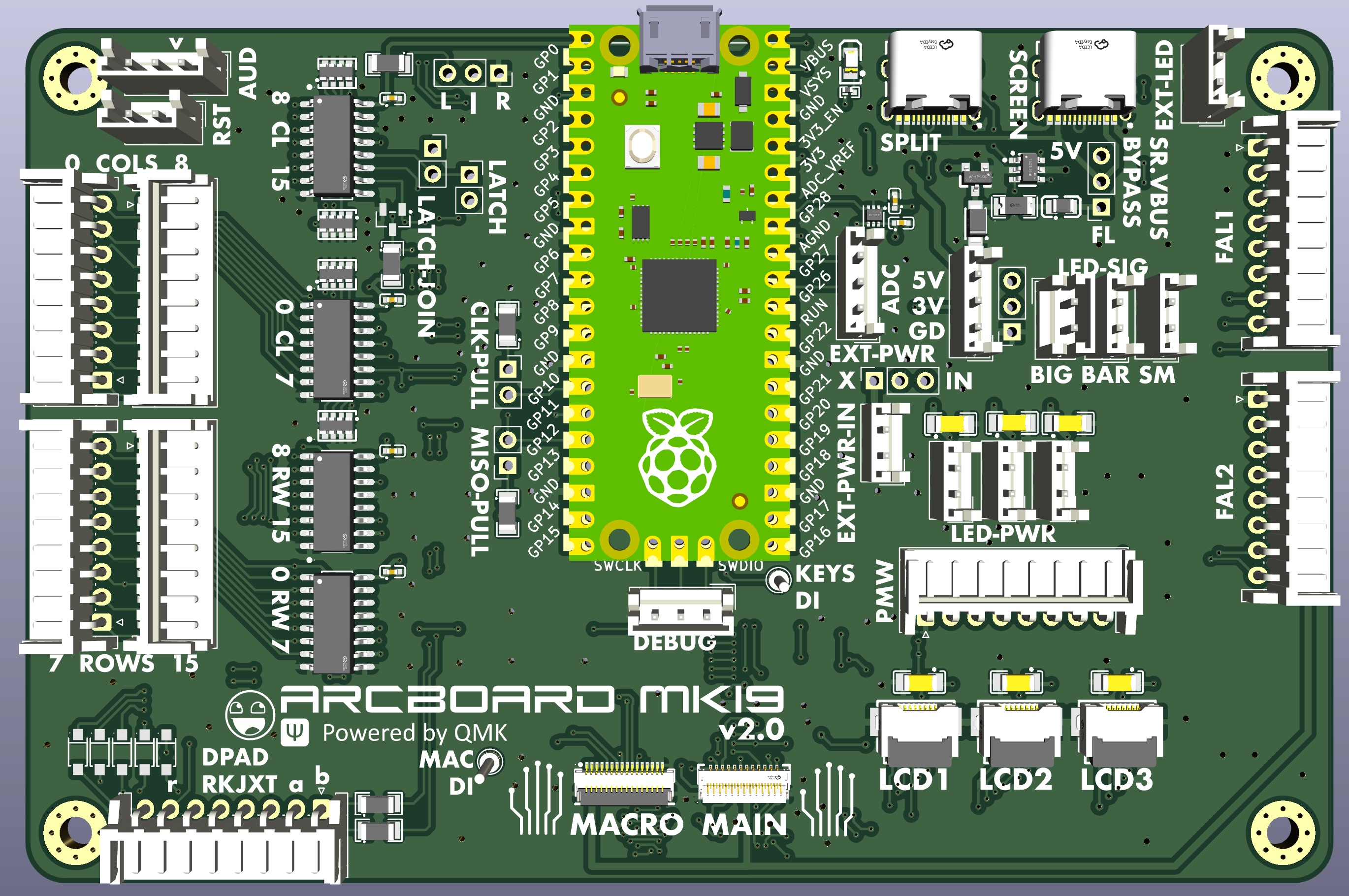
...probably not, which is why I had to design my own pcb. So here it is...
- burkfers (research assistant extraordinaire)
- bomtarnes, chefcooke, walrus, wimads, yingeling, genki, others for design/3d printing help
- Quentin @ BKB & Erik @ Cyboard
- casuanoob (Falcon and diy pcb inspiration)
- tzarc, freznel, KarlK90, Dr. Faustroll, GeorgeN, (and others!) work on shift registers, pcbs, etc
- BKB discord crew; QMK discord; fingerpunch discord (Sadek and Melon, thanks!)
- cardiactuna for the font suggestion
- added rkjxt to dpad connector
- added resistor networks for col shift register pulldown
- relocated cyboard connectors
- fixed a bunch of incorrect pinout orderings
- changed from solder pads to pin jumpers
- re-thought led bypass
- moved TFTs to FFC cables, made 3 of them
- added external 5v power source option
- re-thought the test pins
- Provide a re-usable platform for the arcboards
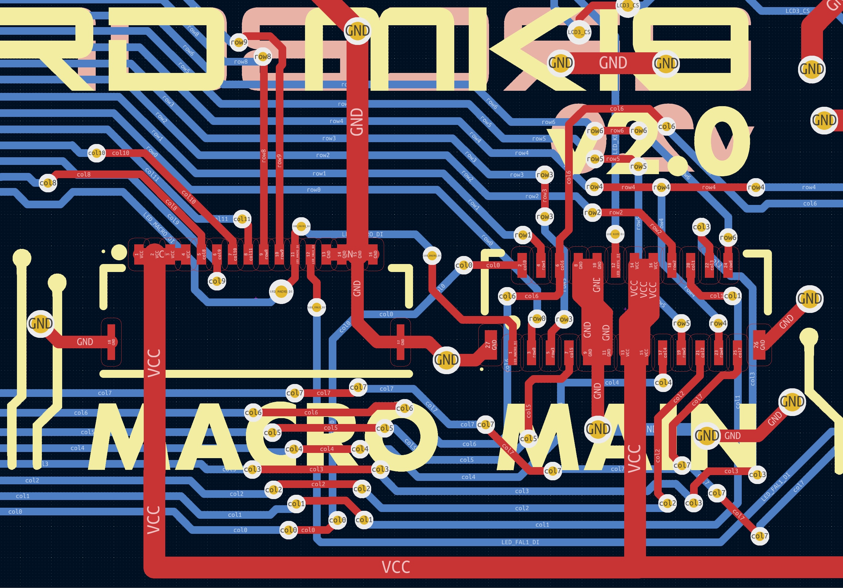
- Make it possible to use the Cyboard flex-pcb system to save on the madness of per-key pcb soldering
- Minimize GPIO usage by moving cols/rows over to shift registers
- Reduce the amount of fiddly soldering and wire stripping a normal hand-wire build requires of you
- USB-C interconnects
- General improvements on the mk17 as a whole
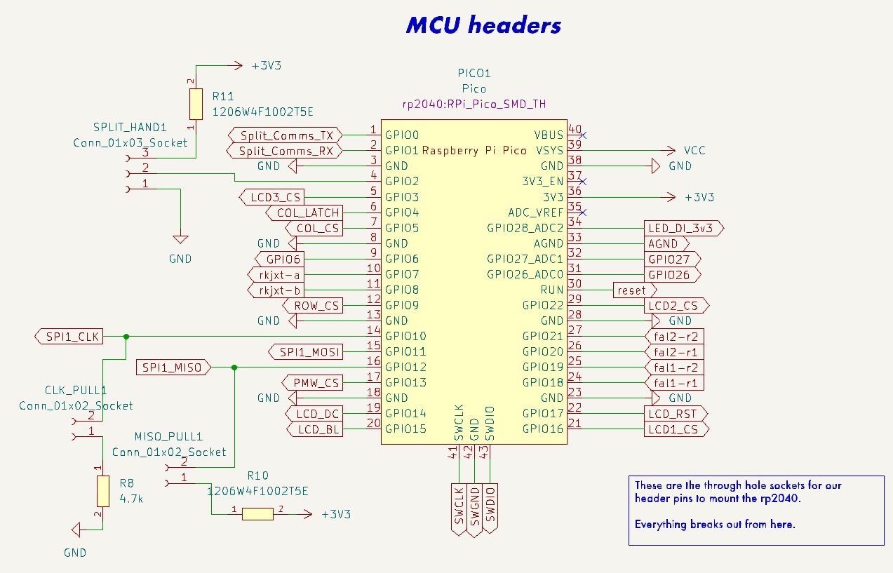
- Raspberry PI Pico (RP2040) footprint - just add pin headers and solder away - or, solder directly to pads
- keys provided through the Cyboard flex-pcb system or, JST-XH 2.54 headers
- macropad using Cyboard flex-pcb keys, custom breakout pcb: https://github.com/christrotter/macropad-pcb (0.5mm pitch 16-pin FFC cable)
- in future I'd just make this a custom FPC cable
- dpad using custom breakout pcbs 5-way switch or RKJXT
- diodes are configured for ROW2COL (to match Cyboard)
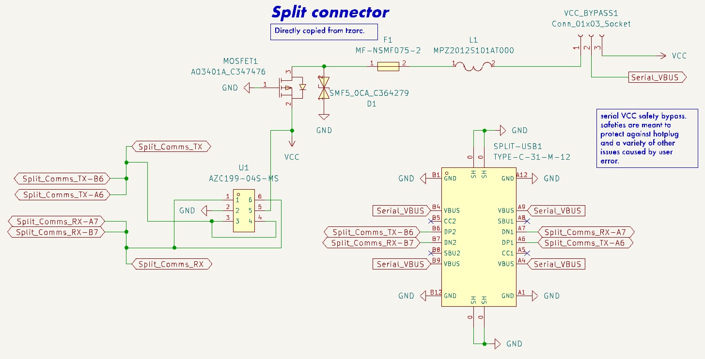
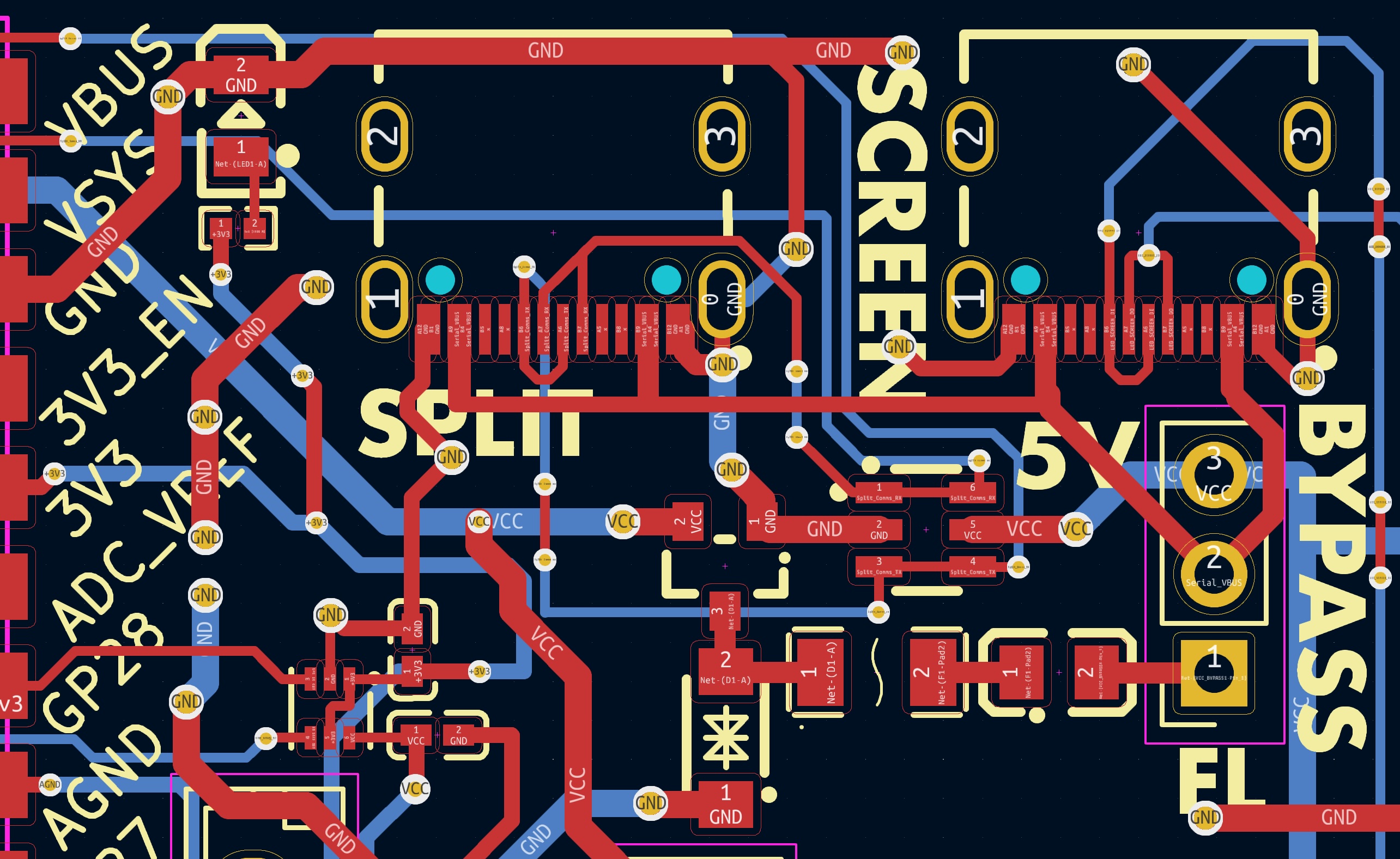
- USB-C split connector w. tzarc-grade voltage protection
- included a solder pad jumper to bypass if needed
- split-handedness via pin (jumper)
- SPI breakouts
- PMW33xx
- 3x TFT LCD (e.g. GC9A01)
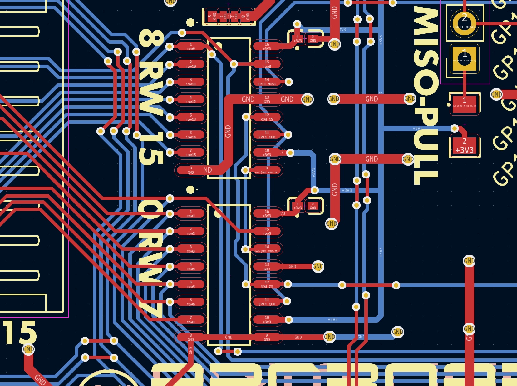
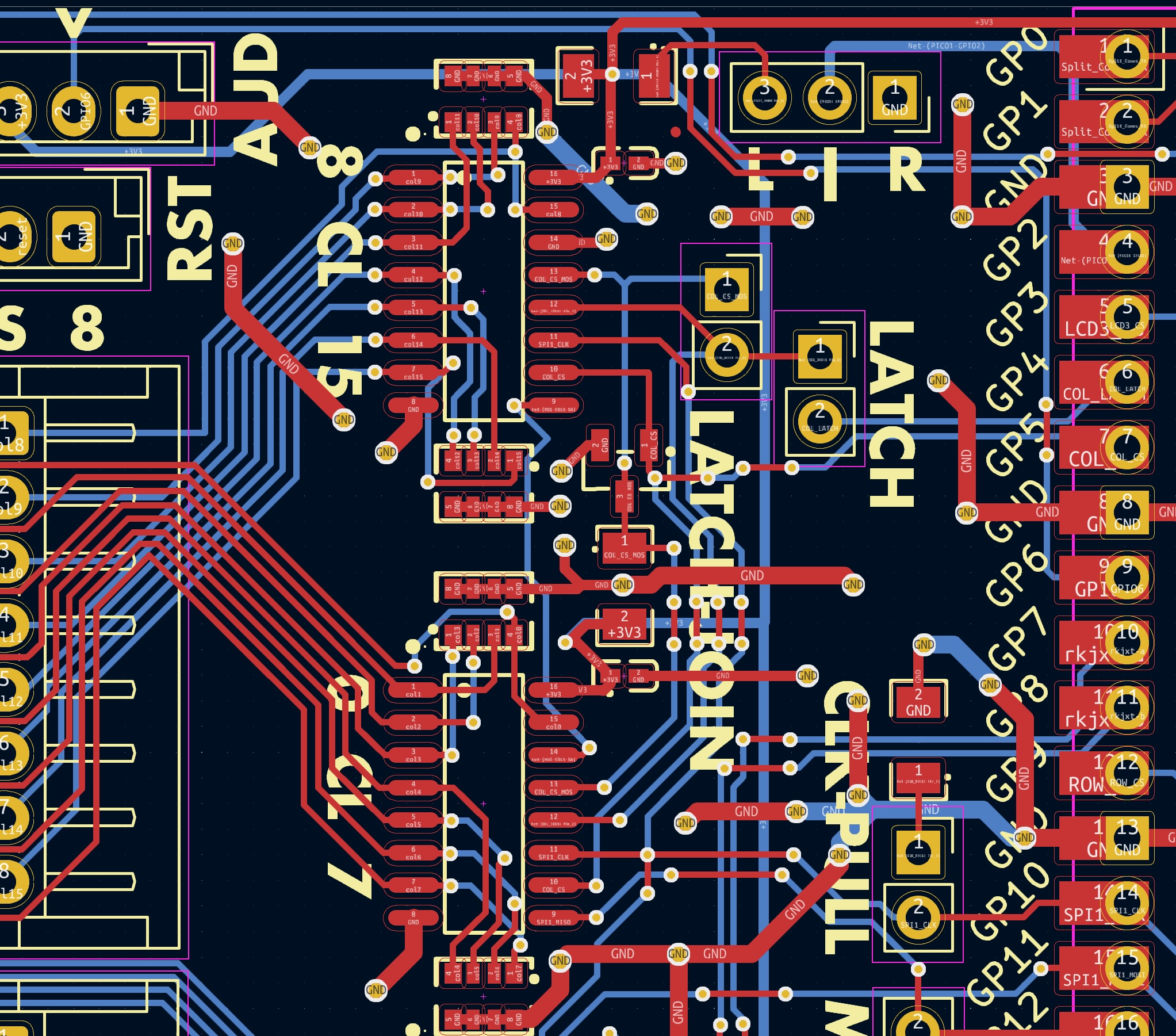
- shift registers (595 for rows, 589 for cols)
- pin breakouts
- power, debug, ADC, audio, reset
- remaining GPIO pins
- test points
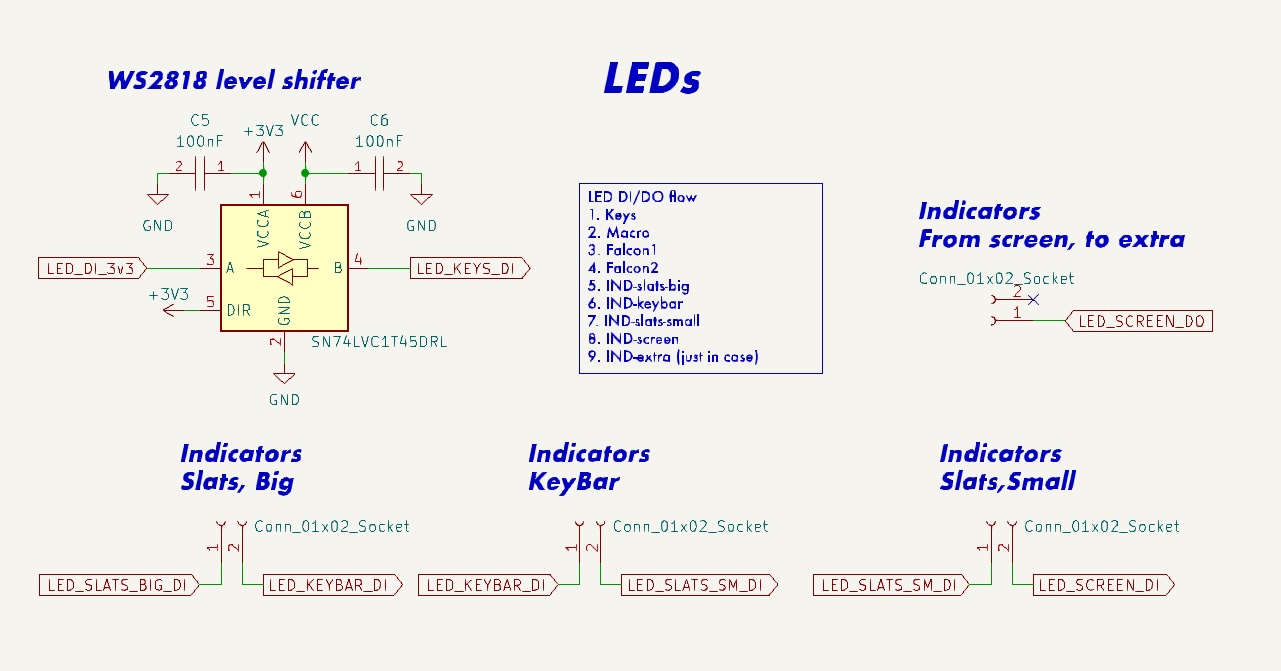
- led breakouts w. bypasses
- keys
- 2x falcon pcbs
- indicator strip
- screen-mounted external indicators via USB-C
- this passes 5v/GND, level-shifted 5v LED DI/DO signal via USB-C cable
- pin for whatever else you want to add to the chain
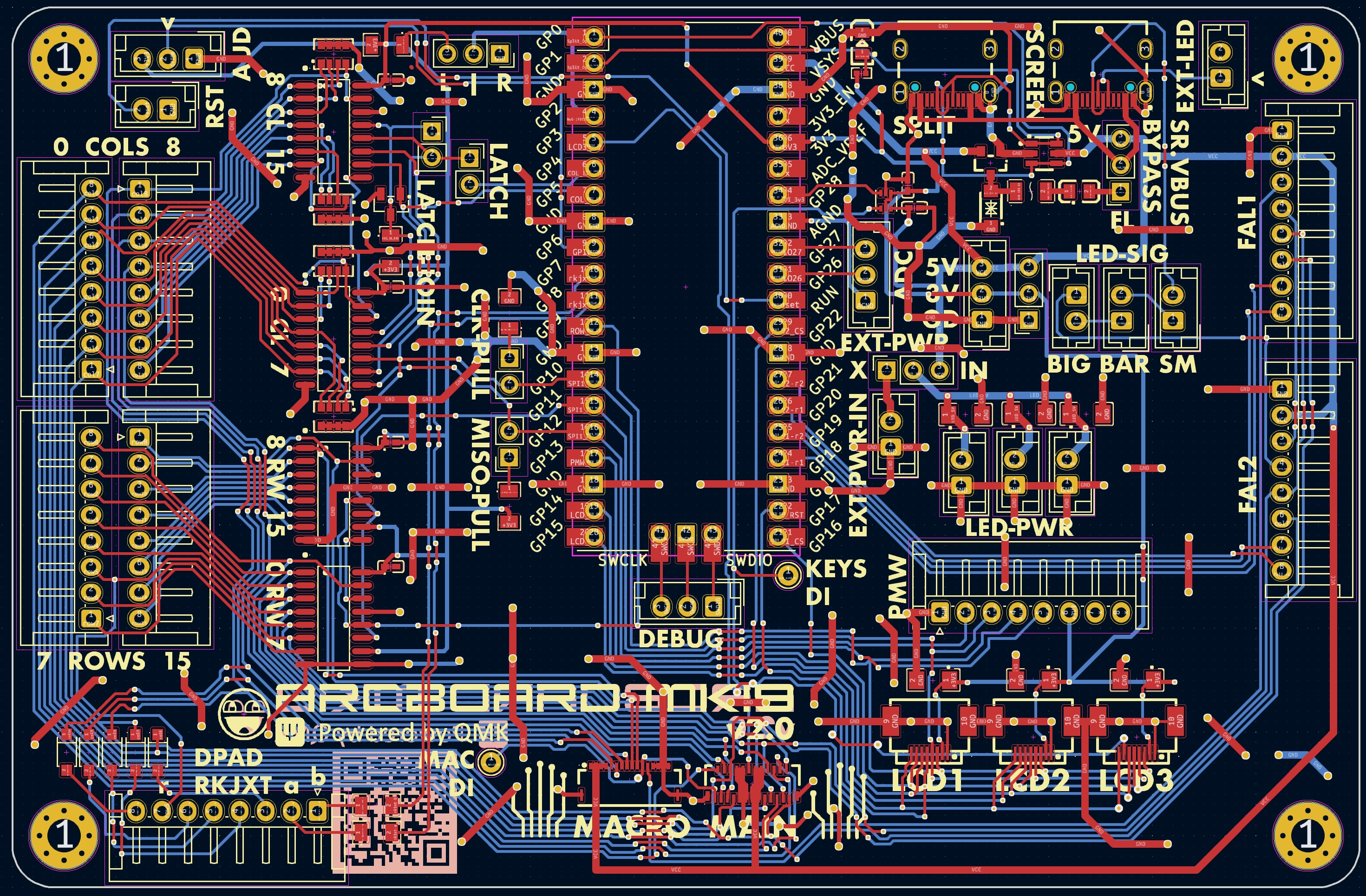
- two-layer pcb w. dual ground planes tied w. vias
- components configured as per datasheets
- bypass capacitors!
- care taken to avoid power running alongside signal for too long
