This repository contains scripts and other code to read and process data collected from Clarius scanners. Each folder contains a specific project, and within includes sample data and matlab/python scripts to read, process, and display the data.
Data that can be acquired from Clarius scanners include:
- RF (raw radio frequency data)
- IQ (quadrature data)
- Envelope (B greyscale)
- To enable raw data capture, the Buffer icon from the modes menu can be pressed. The scanner will then buffer raw data while imaging.
- To enable RF data collection, the RF icon from the modes menu can be pressed. The scanner will then engage internal RF frame capture while scanning in B mode.
- IQ and envelope data is captured by default when RF mode is not engaged; RF and envelope data are captured by default when RF mode is engaged.
- RF streaming is enabled by default when engaging RF mode, and can be toggled through the Stream icon.
- RF mode collects data within the region-of-interest (ROI) placed over the greyscale image.
- While streaming is engaged, RF frames will be interleaved every 3 B/greyscale frames, and thus streamed at a lower frame rate than B. Buffering the RF data will also buffer at this rate.
- When streaming is disabled, RF frames will be interleaved with every B/greyscale frame, thus increasing the frame rate, and affected by the buffering control only.
- Streaming of RF data is used only for visualization within the App, therefore data streamed is not stored for further use; however when users connect to the scanner with the Cast API while RF is streaming, streaming of RF signals will automatically be routed to the API connected device.
- Once imaging is frozen with raw data capture engaged, the capture image or capture cine buttons will automatically download the data from the scanner. Note that in all cases, a packaged .tar file is acquired which then uses an LZO compression scheme for further compressing the raw data. When data is accessed, users should ensure that the proper software to decompress the files is installed on their operating system.
- Downloading raw data over the wireless link can take some time since the packages can be large; for a single frame capture, a download time of 1-3 seconds is typical, for cine captures, where hundreds of frames may be acquired, downloads may take up to one minute.
- During the download, users must wait before imaging once again, progress is shown on the interface while this occurs.
- The scanner is pre-configured with raw data buffers of specific sizes that the system can support to offer stable and consistent imaging, in most cases, up to 10 seconds of raw IQ and RF can be captured, and upwards of 20 seconds of raw B/envelope data. The App can store a cine of up to 30 seconds, it is important to note that the raw data downloaded will always correspond to the latest frames in time. For example, if the cine capture markers are placed at 0-10 seconds within a 20 second capture, it is possible that no raw data will actually be downloaded.
Once an exam has been completed and submitted in the App, the raw data will be accessible through:
- Clarius Cloud when viewing the exam online. Packaged .tar files can be downloaded directly from a browser.
- Exporting the exam to local mobile device storage can be done when ending the exam or through the Exams page. As of App version, 8.6, iOS is now supported to store non image data into the file system.
- If the Cast API is available for the device, raw data can be downloaded via a custom C/C++ program in a similar format to the App, but with immediate access once downloaded from the scanner.
Once raw data files have been accessed onto a PC or other platform, the file structure will look similar to the following:
- Grayscale/Doppler: raw_data.tar
- timestamp_env.raw.lzo -> timestamp_env.raw
- timestamp_env.yml
- timestamp_env.tgc.yml (if auto gain has been used)
- timestamp_iq.raw.lzo -> timestamp_iq.raw (note IQ will be Doppler data when color/power mode enabled)
- timestamp_iq.yml
- RF Mode: raw_data.tar
- timestamp_env.raw.lzo -> timestamp_env.raw
- timestamp_env.tgc.yml (if auto gain has been used)
- timestamp_env.yml
- timestamp_rf.raw.lzo -> timestamp_rf.raw
- timestamp_rf.yml
The .yml files (see YAML markup language definition) contain meta-information about the raw data collected, such as:
- Frame Rates
- Imaging Depth
- Transmit Frequency
- Focal Depth
- Line and Sample Count
- Frame Count
The .tgc files (also in a YAML markup) contain meta-information about the TGC curves applied to each frame. As Clarius imaging defaults to automated TGC usage, each frame may be acquired with a slightly different analog gain curve in order to perform the task of gain adjustment for the user.
The timestamps in the .tgc files will correlate to frame timestamps embedded in the raw data, for example:
timestamp: 235855423246 { 7.00mm, 15.70dB }{ 21.00mm, 26.46dB }{ 35.00mm, 26.82dB }{ 49.00mm, 26.54dB }{ 63.00mm, 28.68dB }{ 77.00mm, 30.29dB }{ 91.00mm, 31.94dB }{ 105.00mm, 33.44dB }{ 119.00mm, 34.87dB }{ 133.00mm, 35.00dB }
The raw data must be decompressed from the .lzo files in the package. Once decompressed they can be open in any piece of software (MATLAB, Python, etc.) that is programmed with reading the file format.
Each .raw file uses the same format, which is:
Header
Timestamp 0
Data 0
Timestamp 1
Data 1
...
Timestamp N
Data N
where the header is formatted as follows:
uint32 id
uint32 numFrames
uint32 numScanLines
uint32 numSamplesPerLine
uint32 sampleSizeInBytes
and each timestamp is in the format of:
uint64 timeInNanoSeconds
and each data block is of size (in bytes):
numScanLines * numSamplesPerLine * sampleSizeInBytes
and the corresponding file size will be:
sizeof(Header) + (numFrames * (sizeof(Timestamp) + (numScanLines * numSamplesPerLine * sampleSizeInBytes)))
-
B Mode data is always in 8-bit greyscale format that are pre scan-converted, meaning they are in ultrasound coordinates, and not pixel coordinates IQ data is always in 32-bit pairs of I and Q, where each I and Q sample is 16-bits. The demodulation frequency depends on the scanner and workflow, and may also vary on scanning parameters and depth.
-
RF data is always 16-bit beamformed samples, where Clarius digitizes natively at 60 MHz. Further down-sampling may be performed to ensure data can be captured, buffered, and transferred properly. At depths < 2cm, 60MHz sampling is applied; at 2 - 4cm, 30MHz sampling is applied; at depths > 4cm, 15 MHz sampling is applied.
The probe has the ability to send a 3.3V CMOS signal from the pins on the rear. Pin 9 outputs the signal, with pins 5 and 8 being connected to ground - a diagram is shown below. One can use the HD3 fan CAD to design a custom connector that will attach to the rear of the probe and output the pulse through a custom BNC or something similar.
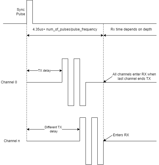
To enable the signal output, open the research menu and press the Sync button (two circular arrows). The signal will be output at the start of each frame acquisition. Note that Clarius' ultrasound sequencing is semi-asynchronous with respect to frame acquisition, meaning the time between each frame will not be exactly the same, but generally within 1 millisecond.
The timing diagram below illustrates the relationship between sync pulse, transmit and receive.

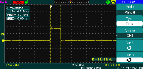
Below is a scope capture of the sync pulse which is a single ended 3.3V CMOS signal.

The following is a non-exhaustive list of low level parameters that can be programmed through the Cast API
Greyscale:
- txFreq: transmit frequency in MHz **
- txFreqInv: transmit frequency in MHz for the inversion pulse **
- txFn: transmit f-number **
- txApt: maximum transmit aperture in elements (2 - 64) **
- txFocus: focus depth in centimeters **
- vpp: positive amplitude in volts (10 - 37) **
- vnn: negative amplitude in volts (10 - 37) **
- ceVpp: positive amplitude in volts for CEUS (10 - 37) **
- ceVnn: negative amplitude in volts for CEUS (10 - 37) **
- steer: image steering in degrees **
- rxFn: receive f-number
- rxFreqShallow: start demodulation frequency in MHz
- rxFreqDeep: end demodulation frequency in MHz
- speedOfSound: speed of sound correction in m/s
- rfDecimation: decimation factor used for IQ data
- envDecimation: decimation factor used for envelope/grayscale data
- rfDecim: decimation factor of the RF signal acquisition
- dyn: dynamic range in dB
- nf: noise floor in dB
Color/Power Doppler:
- cfiPrf: pulse repetition frequency in kHz (range varies per probe/preset) **
- cfiTxFreq: transmit frequency in MHz **
- color steer: steering angle in degrees
- cfiEnsemble: # of ensemble / transmits per line (6 - 16) **
Pulsed Wave Doppler:
- pwPrf: pulse repetition frequency in kHz (range varies per probe/preset) **
- pwTxFreq: transmit frequency in MHz **
- pw gate size: gate size in mm
- pw steer: steering angle in degrees
- pw angle correct: correction angle in degrees
Greyscale:
- sa: synthetic aperture
- pih: pulse inversion harmonics
- trapezoidal: extended field of view for linear probes
Greyscale:
- txPulseGen: transmit pulse **
- txPulsePen: transmit pulse when pentetration mode is active **
- txPulseInv: transmit pulse for the inversion pulse **
Color/Power Doppler:
- cfiPulse: transmit pulse **
Pulsed Wave Doppler:
- pwPulse: transmit pulse **
** Notes that changing this parameter may alter the acoustic output of the transducers making the imaging operate outside of the safety parameters Clarius has programmed into the device


