Copyright (C) 2023 Pat Deegan. All rights reserved.
Source code is released under the GPL (see code/LICENSE), hardware resources under CC BY-SA 4.0 (see hardware/LICENSE)
This is a very simple way to transform the widely used Si5351 modules into a useful lab/workbench tool. The entire purpose is to get access to these three clock generators--which can provide clocks in the low kiloHertz up to hundreds of MegaHertz--with minimal interruption to your workflow.
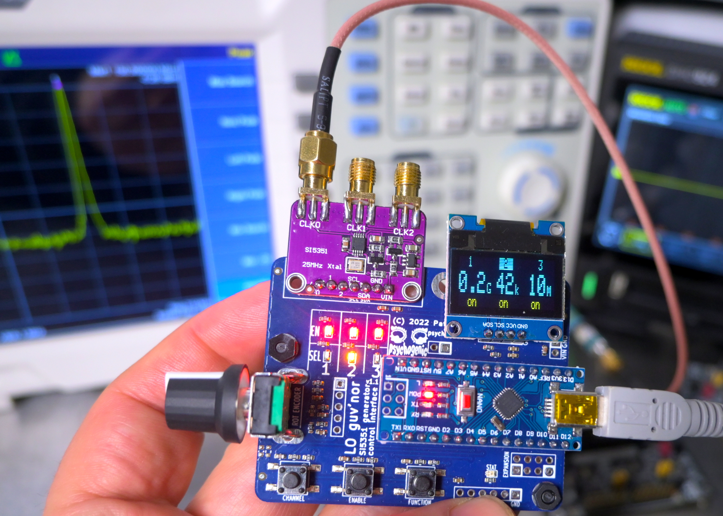
A rotary encoder, an OLED display, and a few momentary switches are all glued together through this basic PCB and bundled with a Nano and the code that provides a quick, and hackable, user interface to the clock generator.
This can be used to prototype Si5351 chip/module use, of course, but is mainly meant to provide mid-range clock signals for driving prototypes and tests. Less capable that a true signal generator--it only outputs square waves--but it offers coverage of a wide band of frequency ranges that go beyond what typical (read: inexpensive) function generators can handle.
Most of the intelligence and function of the system resides in the software, which is a bit more involved than the glue hardware. Full walk-through video, covering the simple hardware, but diving deep into the software created, should be available by December 11th on youtube
Nothing complex about the schematic, which is little more than
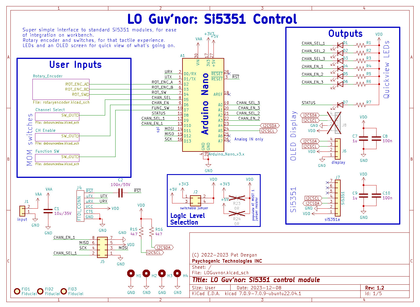
The full schema may be found in the schematic PDF
This version of the boards includes some fixes and additional features, which will be covered in future online documentation and video.