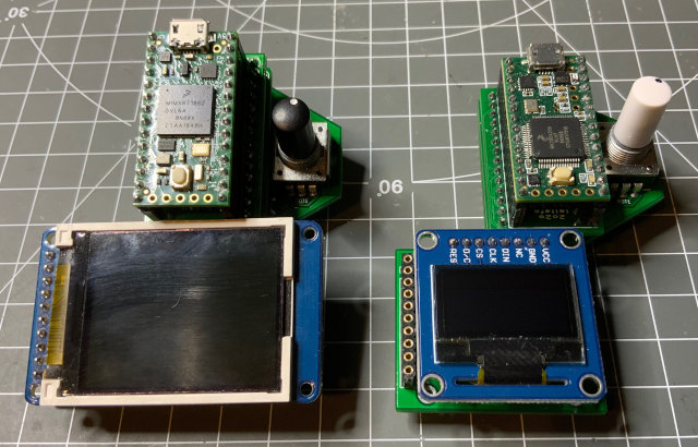
EuroShield Buddy PCB Boards and Arduino Library.
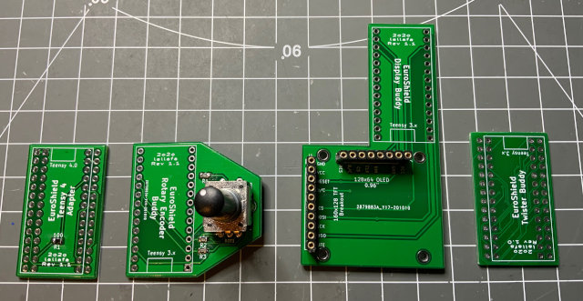
You can combine these boards as you like.
Licensed by Creative Commons Attribution Share Alike 4.0 International
Version: 1.1
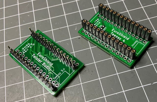
This little adapter board allows to use a Teensy 4.0 board on your EuroShield 1 (short ES) eurorack module.
This is the required re-routing of the Pins:
| Teensy 3.x / EuroShield Pin | Teensy 4.x Pin | Description |
|---|---|---|
| GND | GND | |
| 0 | 0 | Midi IN |
| 1 | 1 | Midi Out |
| 2 | 2 | Button on ES and on Rotary Encoder |
| 3 | 3 | LED 1 |
| 4 | 4 | LED 2 |
| 5 | 5 | LED 2 |
| 6 | 6 | LED 3 |
| 7 | 11 | SPI MOSI |
| 8 | 9 | Display Reset |
| 9 | 21 | Audio BCLK |
| 10 | 10 | SPI CS |
| 11 | 23 | Audio MCLK - A 100 Ohm Resistor is required here! |
| 12 | 12 | SPI MISO |
| Teensy 3.x / EuroShield Pin | Teensy 4.x Pin | Description |
|---|---|---|
| VIN | VIN | |
| AGND | AGND | |
| 3.3V | 3.3V | |
| 23 | 20 | Audio LRCLK |
| 22 | 7 | Audio TX DIN |
| 21 | 15 | Lo Pot on ES |
| 20 | 14 | Hi Pot on ES |
| 19 | 19 | I2C SCL |
| 18 | 18 | I2C SDA |
| 17 | 17 | Rotary Encoder A |
| 16 | 16 | Rotary Encoder B |
| 15 | 22 | Display CMD/Data |
| 14 | 13 | SPI SCK |
| 13 | 8 | Audio RX DOUT |
All Pins are direclty connected expect Audio MCLK is connected via a 100 Ohm resistor.
Version: 1.1
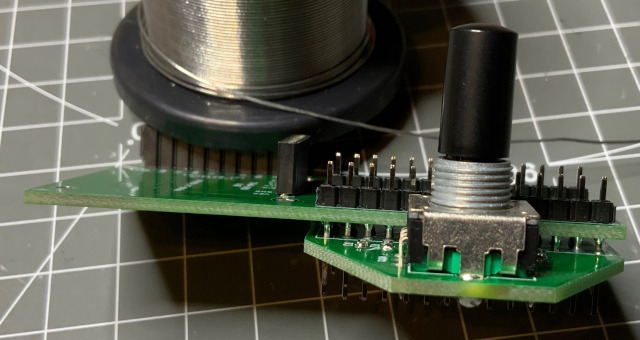
Add a rotary encoder with button to your Euroshield.
| Symbol | Part | Description | Mouser No. |
|---|---|---|---|
| ROT1 | PEC12R-3220F-S0024 | Bourns Rotary Encoder | 652-PEC12R3220FS0024 |
| R1-R3 | SMD 0805 10k | 10k Resistor | 71-CRCW080510K0FKEAC |
Version: 1.1
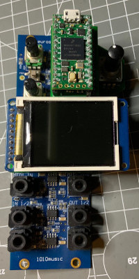
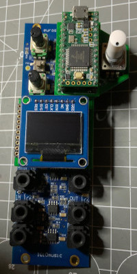
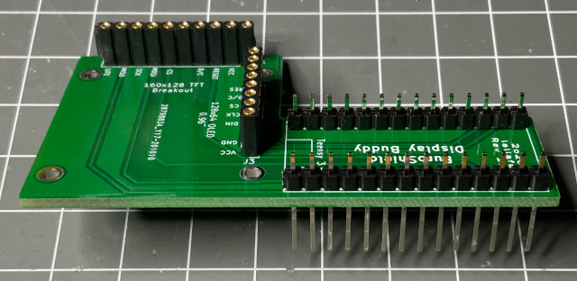
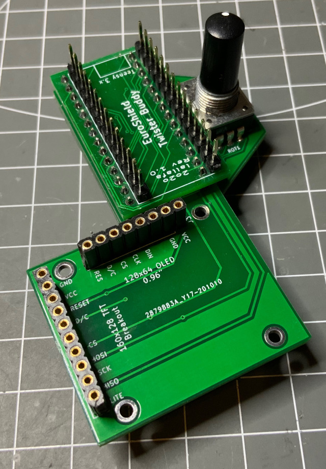
Add an SPI LCD or OLED display to your EuroShield. While the OLED with 128 x 64 fits nicely into the form factor of the shield, the LCD is wider and offers 160 x 128 colored pixels.
The LCD has the following parameters:
- 160 x 128 color TFT LCD 1.8 Inch
- SPI
- ST 7735 Controller
| LCD Pin | Teensy 3.2 Pin | Description |
|---|---|---|
| 1 | GND | GND |
| 2 | 3.3V | 3.3V |
| 3 | 8 | Display Reset |
| 4 | 15 | Display Cmd/Data |
| 5 | - | N/A |
| 6 | 10 | SPI CS |
| 7 | 7 | SPI MOSI |
| 8 | 14 | SPI SCK |
| 9 | 12 | SPI MISO |
| 10 | 3.3V | Display Light |
I use an Adafruit 1.8" Color TFT LCD display with MicroSD Card Breakout (358)
The OLED has the following parameters:
- 128 x 64 monochrome OLED 0.96 Inch
- SPI
- SSD 1306 Controller
| OLED Pin | Teensy 3.2 Pin | Description |
|---|---|---|
| 1 | 3.3V | 3.3V |
| 2 | GND | GND |
| 3 | - | N/A |
| 4 | 7 | SPI MOSI |
| 5 | 14 | SPI SCK |
| 6 | 10 | SPI CS |
| 7 | 15 | Display Cmd/Data |
| 8 | 8 | Display Reset |
Version: 1.0
Turn the Teensy around so that the USB connector points upwards and a connected USB cable gets out of the way and does not obstruct the display.
If you want to build the full stack of buddy boards:
- Start with the display board and solder extra long header pins
- First populate the rotary encoder board (resistors and the encoder) and then solder the board below the display board
- Prepare the Twister Board by adding headers to one side for a Teensy 4.0 setup or a female connector for a Teensy 3.2. If you want to use a Teensy 4.0 then add a female connector to the Teensy 4.0 side of the adapter:
- Solder the prepared Twister Board on top of the Display Board. Make sure that the Teensy USB port on the top side points upwards:
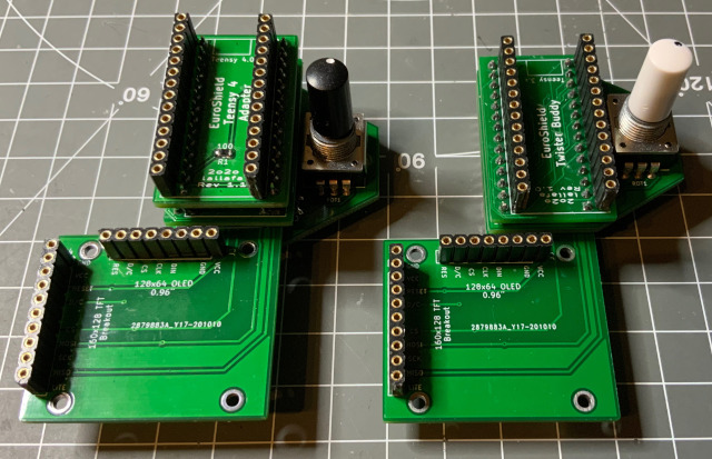
- For a Teensy 4.0 finally solder the Teensy 4.0 adapter board on top of the Twister Board. Note: make sure to add some space between the boards so that the Teensy 4.0 female connector pins do not touch the Display Board pins! Here a both variants: Teensy 4.0 and Teensy 3.2 boards
- Finally add either a LCD or OLED display. Both display types work with both Teensy CPUs.
