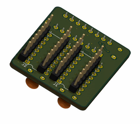
The purpose of this tiny project is to fix a design flaw in the Elwro 800 Junior that causes visible graphical artifacts.
In this repo:
- schematic/PCB project in KiCAD 8 format (in this very directory)
- PDF schematics - color and black&white
- interactive BOM file (you have to download it and open locally)
- Gerber files (in a jlcpcb-compatible ZIP format):
- grafix.zip - single PCB
- grafix_2x_panel.zip - two PCBs panelized
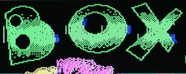
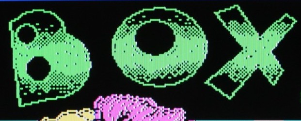
The pictures below were taken before and after installing the GraFIX PCB. . In the first screenshot, green and blue artifacts are clearly visible around the green letters (other examples here).
Junior uses the same screen organization as the ZX Spectrum - every consecutive group of 8 pixels shares the same ink and paper color pair, the pixel value determines whether it is displayed in the ink or paper color. Junior employs two 74LS153 multiplexers for the color selection, this is a purely combinatorial circuit, unfortunately, leading to occasional short (~30ns) glitches visible as artifacts.
Fortunately, the multiplexer outputs remain stable around the rising edges of the CKPIX (pixel clock) signal. The GraFIX mod adds a 4-bit register (74LS175) at the multiplexer outputs, clocked by CKPIX (pixel clock) signal. This effectively latches a stable color value for each pixel, eliminating the glitches.
When soldering the PCB, follow this order: pin headers under U2, then U2 itself, followed by pin headers under U1, and finally U1. Soldering all the pin headers first makes it difficult to solder pins 9 to 16 of U2 due to the small gap between the inner pin headers (been there, done that). See below:
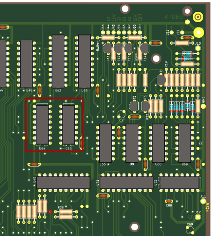
Then you have to unsolder 74LS153 multiplexers and replace them with DIL-16 sockets, now you can insert GraFIX PCB into the sockets. The last step is to connect J3 header on the GraFIX board to CKPIX signal on the Junior PCB with a short piece of wire. The best place to do it is a via close to R38, marked with red X. That's it!


