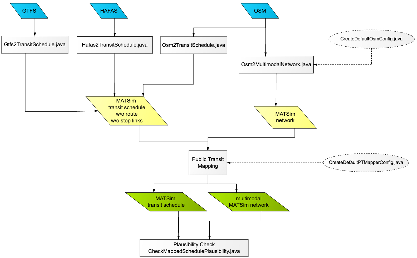
PT2MATSim is a package to convert schedule data such as GTFS, HAFAS or OSM to a completely mapped MATSim schedule.
There are multiple public transit schedule data formats, widely used formats are GTFS and HAFAS. Numerous GTFS feeds are publicly available (see transitfeeds.com or transit.land), otherwise these files have to be obtained from the public transit agency. The Swiss public transit schedule is available in HAFAS format via fahrplanfelder.ch. Public transit data feeds can be converted to unmapped MATSim transit schedules using the classes Gtfs2Transitschedule or Hafas2TransitSchedule. It is possible to convert public transit information from OpenStreetMap files (Osm2TransitSchedule). However, OSM currently does not contain any temporal information, the accuracy of the schedule data varies and is usually not sufficient to be used for simulations.
Unmapped MATSim transit schedule lack information on the links used by vehicles and only contain the stop sequence for transit routes. Generating these links (i.e. the path a vehicle takes on a network) is called "mapping", a process done by the PublicTransitMapper. It implements an algorithm that uses an abstract graph to calculate the least cost path from the transit route's first to its last stop with the constraint that the path must contain a so called link candidate for every stop. The result is a mapped transit schedule and a modified network.
Tools to validate and rudimentarily edit the mapped schedule are also part of the package.
The tools can be used as a maven package or as a standalone utility. In order to create a standalone version the repository needs to be cloned. Afterwards, maven can be used to create a runnable jar:
mvn -Prelease -DskipTests=true
The runnable tools are then located in
pt2matsim/target/pt2matsim-VERSION-release.zip
The zip file contains the runnable jar and its dependencies in the lib/ folder.
The tools can then be run in the following way:
java -cp pt2matsim-VERSION.jar:libs org.matsim.pt2matsim.run.Gtfs2TransitSchedule
The converter is based on the OSM network by M. Rieser (org.matsim.core.utils.io.OsmNetworkReader). However, some changes have been made: The default values for links as well as parameters are stored in a config.xml file. This file allows to define whether an opposite link should be created and to set values for capacity, freespeed and the number of lanes for highway=* and railway=* tags. This also allows to convert rail links. In addition, ways that are only used by buses (i.e. are part of a relation tagged with route=* in OSM) are included in a network. If information on number of lanes or freespeed is available for an OSM way, it is used for the MATSim link. Relevant OSM attributes (for ways and routes) are stored as link attributes in the network.
It is recommended to simplify the network by inserting only one link instead of multiple links between two intersections. The Euclidian distance between the new link's end nodes will less than the the summed up length of the replaced links but the original length can be stored in the length attribute of the new link.
A default config file can be created by running
org.matsim.pt2matsim.run.CreateDefaultOsmConfig
The converter can be run via
org.matsim.pt2matsim.run.Osm2MultimodalNetwork
with the config file path as argument.
The GTFS converter's main job is transforming GTFS trips to MATSim transit routes. Trips and transit routes are not equivalent: A trip defines the stop sequence and the departure time for a vehicle while a MATSim transit route defines the stop sequence but usually has more than one departure time. The time offsets between stops is stored in the routeProfile within the transit route in MATSim. GTFS offers two ways: Either with explicit time stamps in stop_times.txt or as frequencies in frequencies.txt. The converter can use both. Finally, routes in GTFS are like transit lines in MATSim. Stops are converted straight to stop facilities. GTFS offers no explicit information that could be used as isBlocking value for MATSim stop facilities, so false is set by default.
For each trip, a service id defines on which days the trip is carried out. MATSim normally only simulates one day, therefore one sample day has to be extracted from the GTFS feed. Although possible, it is not recommended to use all trips in the feed. The following methods are suggested:
- Define the date to extract all affected trips from it.
- Use the day on which most services run.
- Use the day on which most trips are carried out.
The converter can be run by calling the main() method of
org.matsim.pt2matsim.run.Gtfs2TransitSchedule
with the following arguments:
[0] folder where the gtfs files are located (a single zip file is not supported)
[1]	Which service ids should be used. One of the following:
	- date in the format "yyyymmdd"
	- "dayWithMostServices"
	- "dayWithMostTrips"
	- "all"
[2] the output coordinate system. Use "WGS84" for no transformation. EPSG:* codes are supported.
[3] output transit schedule file
[4] output default vehicles file (optional)
If a feed contains shapes, the shape id is stored in the transit route's description.
HAFAS is a data format used by Swiss public transit agencies (particularly SBB) and other agencies in Europe (e.g. Deutsche Bahn). Data is given in ASCII text files that contain information about operators, stops, vehicles and stop sequences, stop times and additional information. HAFAS data for Switzerland is publicly available and provided by SBB. A report that comes with this exported data provides information on the structure of the files.
Stop facilities are created from the stops defined in the file BFKOORD_GEO (uses WGS84). The transit lines, routes, departures and stop sequences are generated from FPLAN. The file BETRIEB_DE is used to add the agency's name to the transit line id. The reference day is extracted using BITFELD. A default transport mode is assigned to each transit route depending on the vehicle defined in HAFAS. The transport modes correspond to one of the eight transport modes defined in GTFS (see GTFS reference). Optionally, a default vehicle file is provided using predefined values (based on data provided by M. Rieser and P. Bösch) for different vehicle types such as interregional trains, S-Bahn trains or trolley buses.
Converts all files in hafasFolder and writes the output schedule and vehicle file. Stop Facility coordinates are transformed to outputCoordinateSystem.
The converter can be run by calling the main() method of
org.matsim.pt2matsim.run.Hafas2TransitSchedule
with the following arguments:
[0] hafasFolder
[1] outputCoordinateSystem. Use "WGS84" for no transformation. EPGS:* codes are supported.
[2] outputScheduleFile
[3] outputVehicleFile
OSM offers tags to specify spatial public transit data on stop locations and transit routes. The converter provided as part of the package creates an unmapped transit schedule from OSM data. It creates stop facilities from OSM nodes with the tag public_transport=stop_position. Relations with the tag route=* are converted to transit routes. These transit routes contain only stop sequences. Link sequences are not converted even if they are available. The transport mode is set based on the respective route=* tag value of the relation.
The quality of the generated transit schedule for a region depends largely on the accuracy of the data in OSM. Often route data is either inconsistent or not even available. The lack of naming conventions further complicates using the data. In addition, OSM does not offer any tags to store temporal information. Thus, departure times and stop offsets have to be gathered from other sources.
The converter can be run via
org.matsim.pt2matsim.run.Osm2TransitSchedule
with the following arguments
[0] osm file
[1] output schedule file
[2] output coordinate system (optional)
All input parameters are defined in a config file, a default config file can be created via
org.matsim.pt2matsim.run.CreateDefaultPTMapperConfig
The whole schedule is mapped to the network. In cases where only subsets should be used (e.g. for a region), the schedule needs to be filtered beforehand.
The Public Transit Mapper is run via
org.matsim.pt2matsim.run.PublicTransitMapper
with a config file as input argument.
A reference link for each stop and the path between those referenced links have to be defined. To generate the paths, the following input data is usually available for each transit route: stop sequence, stops with coordinates and a network as a directed graph.
The algorithm works without using any additional GPS data. It is assumed that a public transit vehicle can access a stop by passing a link which is referenced to the stop. Depending on the input data, stop locations are not available, i.e. multiple stop locations on different roads are combined to one parent stop with the same name in the schedule. When two lines use a stop at an intersection there might be one to four actual stop locations.
The implemented algorithm (called pseudo routing algorithm) looks at the whole route to define the best link for each stop. It is also possible that more than one optimal link can be found for a stop. The algorithm calculates the least cost path from the transit route's first to its last stop with the constraint that the path must contain a link candidate of every stop. For each transit route, the algorithm consists of the following steps:
- Find link candidates for each stop.
- Create a pseudo graph using the link candidates as nodes. Add a dummy source and destination node to the pseudo graph.
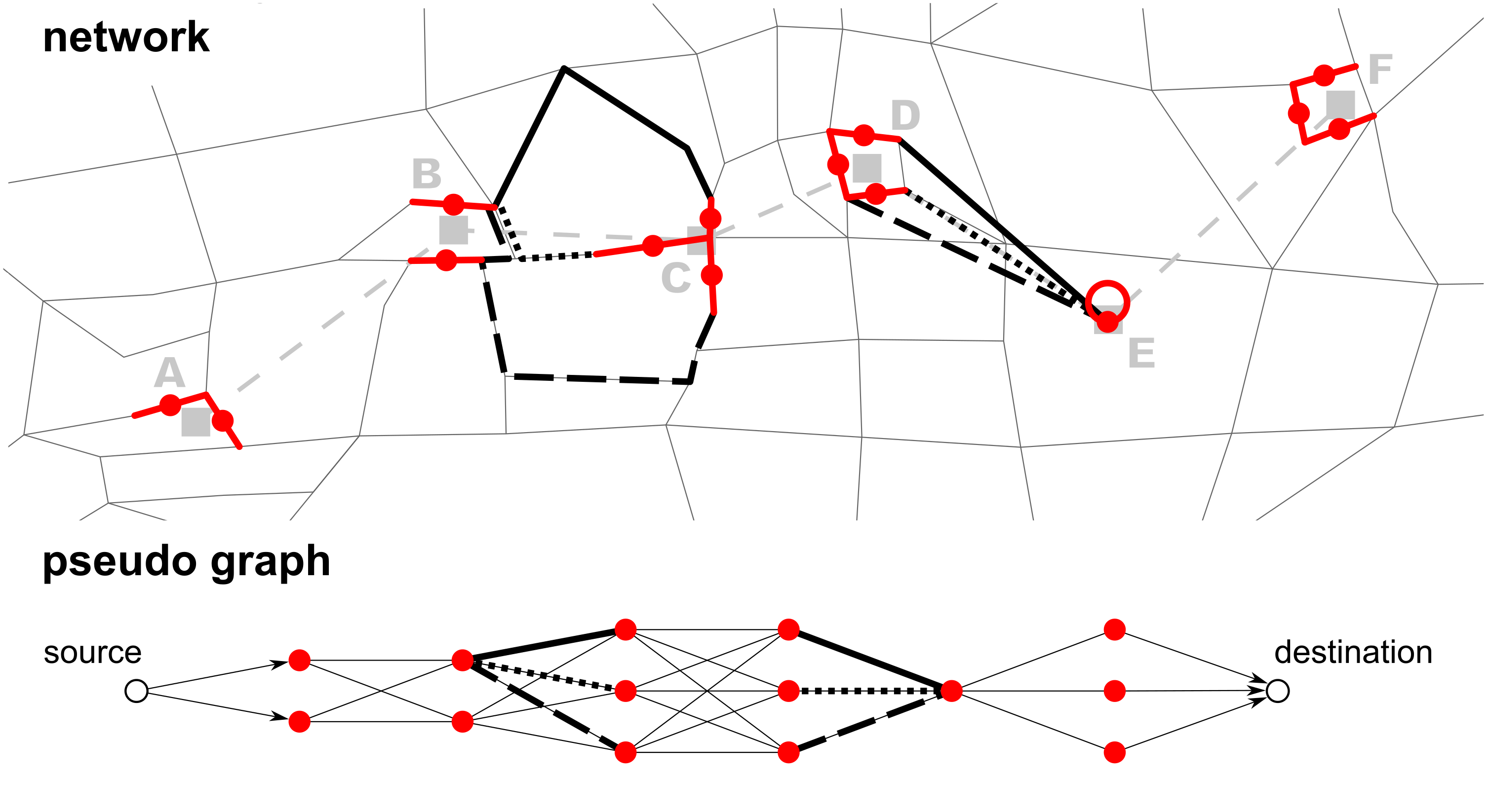
- Calculate the least cost path between each link candidate pair. This path is represented by an edge in the pseudo graph, connecting two link candidate nodes. The edge weight is the path's travel cost plus half the travel cost of the two link candidates it connects.
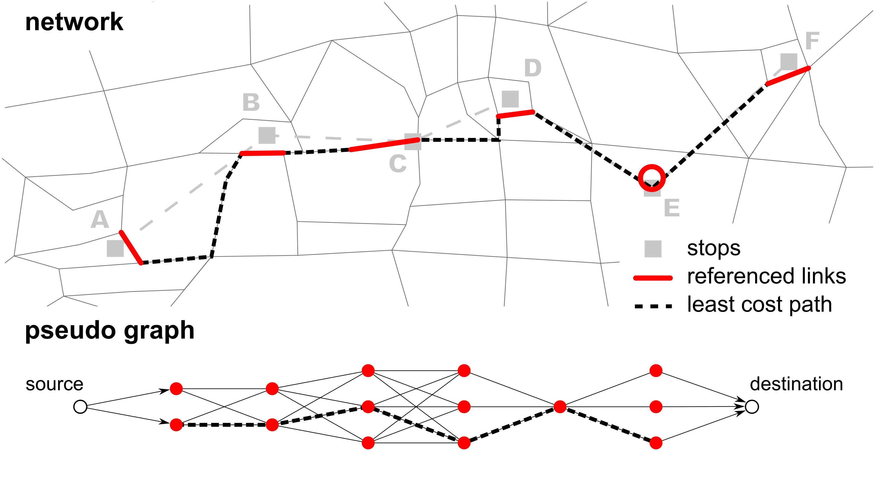
- Calculate the pseudo least cost path from the source node to the destination node in the pseudo graph. The resulting least cost path contains the best link candidate for each stop.
- Create the link sequence. Each stop is referenced to a link (given by the best link candidate that is part of the pseudo least cost path). The least cost path on the real network between the referenced links is used to create the network path for the transit route.
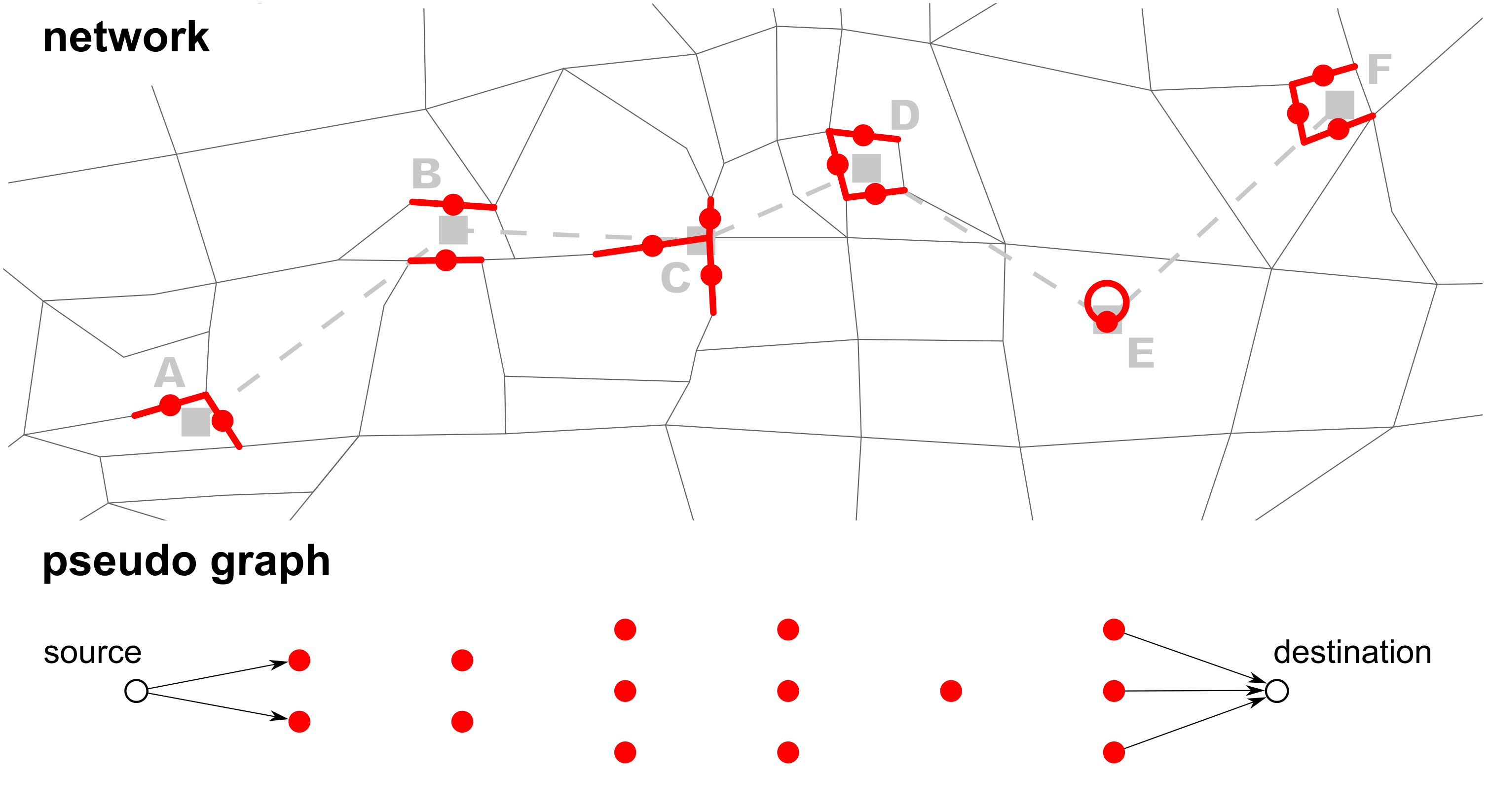
 Steps 1 & 2: Finding link candidates and creating a pseudo graph
 Step 3: Calculate least cost path between each link candidate on the network
 Steps 4 & 5: Calculate least cost path on the pseudo graph. Use this path to create link sequence on network
First, a set of link candidates is created for each stop facility and schedule transport mode. For all nodes within nodeSearchRadius the in- and outlinks are fetched and sorted in ascending order by their distance from the stop facility. The other link candidates search parameters are defined for each schedule mode in the respective linkCandidateCreator parameterset. maxNClosestLinks defines how many links should be considered for each stop facility. This limit is not strictly enforced: When the limit is reached, the last link's opposite link is still added to the set. Further, after the limit has been reached, the distance of the farthest link to the stop facility is multiplied by linkDistanceTolerance and all additional links within this distance are added as well. This is used as a soft constraint to include links with almost the same distance from the stop facility. However, no links farther than maxLinkCandidateDistance from the stop facility are used.
The implementation allows to manually define link candidate beforehand in the config (in a manualLinkCandidates parameterset or a separate csv file (parameter manualLinkCandidate_CsvFile). This helps mapping with complicated rail stations. Stop facilities with no link within maxLinkCandidateDistance are given a dummy loop link at their coordinates: A node is added at the coordinate and a dummy loop link is added to the network with the added node as source and destination. The loop link is referenced to the stop facility and is set as its only link candidate. useArtificialLoopLink defines if such an artificial loop link should be created regardless of the other parameters. Tram, subway, ferry, funicular and gondola routes are normally mapped with artificial links.
The config parameterset modeRoutingAssignment defines for a transport mode what links a transit route of this mode is allowed to use. For example, transit routes with schedule mode bus can only use links with "bus" or "car" as modes. Similarly, all transit routes with the transport mode rail can only use rail links. If no assignment for a schedule transport mode is given, all transit routes using that mode are mapped with artificial links between stops.
To calculate the least cost paths as part of pseudo routing, a router is needed for every transport mode. To create these routers, mode separated networks are generated. Then an A* router for each of these networks is initialized. The networks are filtered according to the modeRoutingAssignment. The router uses one of two link travel costs: either linkLength or travelTime, defined in parameter travelCostType.
During this step the best sequence of link candidates for each transit route is calculated. While routing on the network uses an A* router, least cost path search on the pseudo graph is done with a separate Dijkstra implementation.
Artificial links connect the toNode of a link candidate with the fromNode of the next link candidate. Artificial links are added to the network in two cases: When no path on the network between two link candidates can be found or if the least cost path has costs greater than a threshold. This threshold is defined as maxTravelCostFactor times the minimal travel costs. The minimal travel costs depend on the parameter travelCostType: If it is linkLength, the beeline distance between the two stops is used. If it is travelTime, the minimal travel cost is equivalent to the travel time needed based on the arrival and departure offsets of the two stops. All artificial links (including loop links for stop facilities) and nodes have the prefix "pt_".
The step "PseudoRouting" creates PseudoRoutes for each transit route, each of which contains a sequence of PseudoRouteStops. A PseudoRouteStop contains information on the stop facility, the link candidate as well as departure and arrival offsets.
This pseudo routing step can be parallelized using multiple threads (numOfThreads). For each thread a queue of transit lines is handled. However, the search for the shortest path between link candidates uses the routing algorithms provided in the MATSim core which are not thread safe. Access to the mode separated routers had to be synchronized.
Since the shortest paths on the network have been calculated, the optimal link sequence for each transit route is known. After this step, all artificial links are added to the network.
After all pseudoRoutes have been created, most likely there are multiple best links for a stop facility because different routes use different links. For each of these links a "child stop facility" is created. It has the same name and coordinate as its parent stop facility but it has a link referenced. The id of the child stop facility is generated by combining the parent stop id and the link id, connected by the string ".link:". For example the child stop facility of parent stop 64587 which is connected to the link 432 would get the id "64587.link:432". Using the same connection string for all parts of the package allows to infer the parent stop id based on the given stop facility id.
Since it is now known which link candidates and thus child stop facility each transit route uses, route profiles (stop sequences) for all transit routes can be created.
Pseudo routing is finished after the previous steps. However, some artifacts remain in the schedule and the network. By default, stop facilities that are not used by any transit route are removed (removeNotUsedStopFacilities). The freespeed of artificial links is set according to the schedule: For all transit routes the minimal necessary freespeed to ensure they are on schedule is calculated. The highest minimal freespeed of all transit routes of a link is used as the link's freespeed. This process can be done for other link transport modes as well (defined in scheduleFreespeedModes). It is recommended to do this for rail.
The transport mode of each transit route is assigned to its used links. Links that are not used by a transit route are removed. This can clean up and simplify rail networks. Links which have a mode defined in modesToKeepOnCleanup are kept regardless of public transit usage.
While the TransitScheduleValidator is a good first indicator of the quality of a schedule, it does not check how plausible a transit route is. Possible implausibilities are for example if a route has loops, if sudden direction changes happen between links (u-turns) or if the travel times given by the schedule are cannot be met. If the travel time between two stops is higher than the scheduled time this points to either a too long (i.e. wrong) route or too low freespeed values on the network.
The package provides a plausibility check via
org.matsim.pt2matsim.run.CheckMappedSchedulePlausibility
that looks for implausible parts of a route and warns accordingly. It needs the input:
[0] schedule file
[1] network file
[2]	coordinate system (of both schedule and network)
[3]	output folder
The following files are created in the output folder:
- allPlausibilityWarnings.csv: shows all plausibility warnings in a csv file
- stopfacilities.csv: the number of child stop facilities for all stop facilities as csv
- stopfacilities_histogram.png: a histogram as png showing the number of child stop facilities
- shp/warnings/WarningsLoops.shp: Loops warnings as polyline shapefile
- shp/warnings/WarningsTravelTime.shp: Travel time warnings as polyline shapefile
- shp/warnings/WarningsDirectionChange.shp: Direction change warnings as polyline shapefile
- shp/schedule/TransitRoutes.shp: Transit routes of the schedule as polyline shapefile
- shp/schedule/StopFacilities.shp: Stop Facilities as point shapefile
- shp/schedule/StopFacilities_refLinks.shp: The stop facilities' reference links as polyline shapefile
Shapefiles can be viewed in a GIS, a recommended open source application is QGIS. It is also possible to view them in senozon via. However, no line attributes can be displayed or viewed there.
